Description
Technical Specifications
| Parameter | Specification |
|---|---|
| Model | ANR10D |
| Manufacturer | Yokogawa |
| Product Family | Field Control I/O (FIO) |
| Unit Type | ER Bus Node Unit (remote node) |
| Bus Type | ER bus |
| Bus Redundancy | Dual-redundant configuration |
| Installation | 19-inch rack mounting |
| Host Interface | ER bus connection to a compatible host node with ER bus interface |
| I/O Support | Compatible FIO analog and digital I/O modules |
| Power Supply | Configuration-dependent; verify complete suffix |
| Environmental Option | Basic or ISA G3, depending on suffix |
| Explosion Protection | Depends on suffix and ordered option |
| Dimensions / Weight | Confirm against the applicable general specification and assembled configuration |
The manufacturer’s general specification identifies ANR10D as a dual-redundant ER Bus Node Unit for FIO. The complete order code determines important configuration details, so the base model alone is insufficient to establish every electrical or environmental rating.
Product Overview
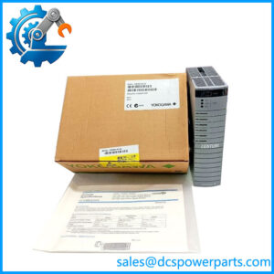
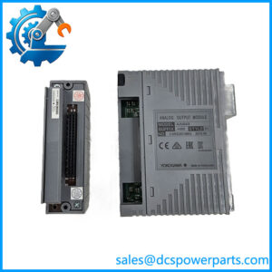
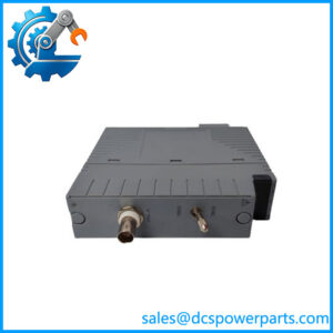
The Yokogawa ANR10D is a rack-mounted remote I/O node used in distributed process-control installations. Within the FIO architecture, remote nodes allow compatible analog and digital I/O modules to communicate with a host node and the associated Field Control Unit (FCU). The ANR10D uses the ER bus for this connection and is intended for installations that require a dual-redundant bus arrangement. Its role is to provide the node infrastructure for field I/O, not to execute the process-control application independently.
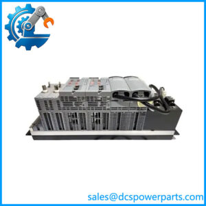
The unit is designed to accommodate the required node-level hardware, including power-supply, bus-interface, and I/O modules according to the system configuration. The dual-redundant arrangement is a key distinction from the single-bus ANR10S. However, redundancy depends on the complete system design: compatible host hardware, correct bus cabling, appropriate interface modules, configured redundancy, and properly commissioned communication paths. Installing an ANR10D by itself does not establish end-to-end redundancy.
For procurement and replacement work, verify the complete ANR10D order code rather than ordering by the base model alone. Yokogawa documentation lists different supply and environmental configurations, including options for ISA G3 environmental conditions and explosion protection. These options can affect suitability for a particular cabinet or plant area. Confirm the installed suffix, host node, bus-interface arrangement, I/O module compatibility, and required certifications before approving a replacement.
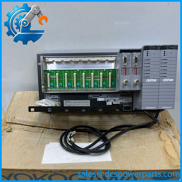
ANR10D
Major Features and Advantages
1. Remote I/O node architecture
The provides the node-level infrastructure for remote field I/O. Compatible I/O modules installed in the node acquire field signals or provide outputs under the control of the host system. This arrangement supports distributed I/O layouts where field wiring and signal conditioning are located away from the main control equipment.
2. Dual-redundant ER bus
The is the dual-redundant ER Bus Node Unit in the ANR10 family. Redundant communication paths can help maintain I/O communication when a supported path or associated component fails. The actual behavior during a fault depends on the installed interface hardware, cabling, system configuration, and approved redundancy design. Confirm that both paths are installed and commissioned; a dual-redundant node connected through only one usable path does not provide full bus-path redundancy.
3. Rack-mounted node format
The unit is specified for 19-inch rack mounting, making it suitable for compatible Yokogawa cabinet layouts. During replacement, check rack space, mounting hardware, module arrangement, cable routing, and cabinet access. Mechanical compatibility should be verified against the installed assembly and applicable installation drawings rather than inferred from the product name.
4. Support for modular field I/O
The node architecture supports compatible analog and digital I/O modules. The exact cards available for installation depend on the host system, node configuration, and applicable module specifications. For example, a digital input module and an analog input module have different signal requirements and cannot be treated as interchangeable merely because both fit within an I/O architecture.
5. Configurable power and environmental options
Yokogawa documentation lists multiple power-supply and environmental variants for the family, including ISA G3 and explosion-protection options. These distinctions matter when selecting spares for cabinets with specific electrical supplies or environmental requirements. Do not infer the installed unit’s power input or hazardous-area suitability from the base designation.
6. Maintenance of existing FIO installations
For a plant operating a compatible Yokogawa FIO system, a correctly specified can support maintenance of the existing remote I/O architecture. Before replacement, confirm the host node, ER bus interface, redundancy arrangement, installed I/O modules, and the full order code. This avoids a common maintenance error: matching the main model number while overlooking a supply or protection suffix that is important to the installation.
Typical Applications
- Remote process I/O: Connecting compatible field I/O modules to a host control node through the ER bus.
- Distributed instrument cabinets: Supporting remote collection of analog measurements and discrete status signals where the FIO architecture is used.
- Dual-redundant communication layouts: Serving as the remote node in a system designed with redundant ER bus paths.
- Process equipment monitoring: Providing the node infrastructure for I/O modules that monitor pressure, flow, temperature, level, and discrete equipment states, depending on the installed module types.
- Plant expansion: Adding remote I/O capacity where the host system, node count, communication topology, and installed software licenses support expansion.
- Legacy system maintenance: Replacing a failed node in an established FIO installation after verifying the full hardware configuration.
- Control-system migration planning: Assessing whether existing remote I/O hardware can remain in service or should be replaced as part of a broader system upgrade.
These are applications of the documented FIO node architecture. Actual support depends on the host FCU, node expansion limits, bus interfaces, I/O module selection, and system release. The should not be described as a universal interface for unrelated PLC or DCS platforms.
Related Products
| Model | Relationship to |
|---|---|
| ANR10S | Single-bus ER Bus Node Unit; differs from in bus redundancy configuration. |
| ANB10D | Dual-redundant ESB Bus Node Unit for local-node applications; uses a different bus role. |
| ANB10S | Single ESB Bus Node Unit for the corresponding local-node architecture. |
| EB401 | ER Bus Interface Master Module used in the documented FIO architecture to connect ER bus node units to the host node. |
| ADV151 | 32-channel, 24 V DC digital input module for compatible FIO node units. |
| ADV551 | 32-channel, 24 V DC digital output module for compatible FIO configurations. |
| AAI143 | Analog input module for compatible Yokogawa FIO configurations; check the precise suffix and system support. |
These models are related through the FIO node and I/O architecture, but they perform different functions. Confirm the system general specifications before substituting a node, interface module, or I/O card.
Installation and Maintenance
Before replacing a Yokogawa , identify the complete model and suffix on the nameplate. Record the power-supply configuration, environmental and explosion-protection options, host node, ER bus interface, and installed I/O modules. Use the applicable Yokogawa system and installation documents to establish the approved replacement procedure.
- Follow the site isolation procedure. Apply the plant’s lockout/tagout and control-system maintenance rules. Do not assume that the node can be removed under power unless the applicable documentation explicitly permits it.
- Verify the host connection. Confirm that the intended host node and ER bus interface support the target node and that the approved bus topology is documented.
- Inspect both communication paths. For a redundant installation, check the condition and routing of both ER bus paths, connectors, and associated interface hardware.
- Check power configuration. Verify that the replacement’s supply option matches the cabinet’s available power and the installed node configuration.
- Confirm module compatibility. Compare the installed I/O modules and node arrangement with the system documentation before transferring or replacing cards.
- Commission the node. Follow the approved procedure to verify node status, bus communication, redundancy behavior, and representative I/O points. Test failover only through a controlled procedure authorized for the plant.
- Document the change. Record the full model code, revision information, installed configuration, test results, and any changes to the system records.
If communication fails after installation, inspect power, connectors, bus cabling, host interface configuration, and the redundancy arrangement before concluding that the node itself is defective. Never force a bus connection or substitute a different node type solely because it has a similar physical format.
Product Assurance and Procurement Checks
For procurement, the most important requirement is to verify the full configuration. Request a clear nameplate image or written confirmation of the complete suffix, power-supply option, environmental classification, explosion-protection status, and any additional option codes. Confirm that the offered unit matches the host node and ER bus arrangement at the installation site.
For used or refurbished units, ask what inspection and functional testing have actually been completed. A visual inspection can identify damage or corrosion but cannot prove correct communication or redundancy operation. If the unit is intended for a critical process, use the site’s approved incoming inspection and commissioning procedures before returning it to service.
For new or surplus stock, verify traceability, packaging condition, warranty terms, and the supplier’s stated condition. Do not assume that a listing marked “new” establishes original manufacturer provenance or confirms the exact hardware revision. Where the system is being expanded, check node-count restrictions, required expansion licensing, and the applicable system documentation before purchase.
Procurement recommendation: The Yokogawa is a dual-redundant ER Bus Node Unit for FIO remote I/O. Match the complete suffix and verify the host interface, both bus paths, power configuration, and environmental requirements before treating a proposed unit as a compatible replacement.