Description
Product Overview
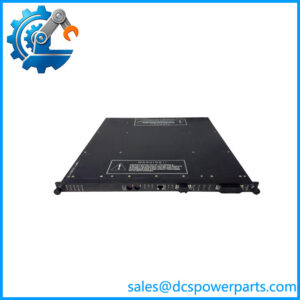
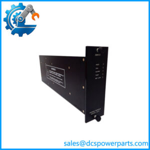
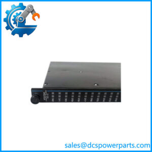
DO3401 is Model 3401, the digital output module of the Trident safety controller, and the first thing to notice about it is that it has sixteen points where the input cards have thirty-two. The reason is arithmetic rather than economy: every point on this card carries a load current, and the front panel is the same 44 mm. Sixteen points, commoned, high-side solid-state switches, 24 VDC nominal with an operational window of 15 to 30 VDC and a 33 VDC ceiling. The result is a card whose job is not to read the process but to move it — to pull a solenoid, close a pilot valve, energise an interposing relay or hold a permissive into a starter.
The output stage is where this module differs from anything else on the platform. Each of the three isolated channels accepts data from its own main processor and drives its own set of switches; those switches are arranged in the patented Quad Voter configuration, parallel-series paths that pass power only when two of the three channels command them closed. The paths are redundant in both directions, so a single stuck switch does not hold an output on and a single open switch does not prevent it from closing. That is the difference between voting in software and voting in copper, and it is why a 3401 can be trusted to de-energise a valve when one channel has failed.
Current behaviour is specified in two regimes, which is a detail worth reading twice. In normal switching the output self-limits below 4.8 A with 3.0 A typical; in degraded mode — a channel leg lost — the point still operates, self-limiting to about 1.5 A typical with a floor of 0.7 A. Translated to the plant: a failed channel does not take the point out of service, and a shorted field solenoid does not take the module down with it. That degraded capability is a specification, not hope, and it is what allows a unit to keep running to the next planned outage instead of tripping on a card fault.
Diagnostics run continuously through the Output Voter Diagnostic routine. For each point the module periodically exercises the voting paths and detects stuck-on and stuck-off points within 500 milliseconds, along with stuck switches and their drive circuitry. A stuck-on output is the dangerous direction — a valve that cannot shut — and half a second to detect it is the kind of number a safety case can use. The price of the technique is a diagnostic glitch: the output is momentarily disturbed, published as under 2 ms maximum and about 500 µs typical. On a solenoid valve or a relay coil that is invisible. On a device that responds in microseconds it is not, and that is a real limit rather than a footnote.
Loop-back closes the loop on the physical point. The module reads the output state back through the same threshold bands the inputs use — 0 to 5 VDC off, 6 to 14 VDC transition, 15 to 30 VDC on — scanning all sixteen points in under a millisecond, and raising field alarms for loss of field power and for an output point shorted either on or off. Off-state leakage is held below 1 mA, and the on-state drop is under 1.0 VDC at 1.5 A, which is both a load-voltage consideration and a heat consideration inside the cabinet.
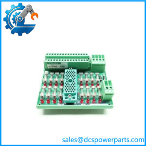
The carrier decides the current policy. On the standard Model 2401 baseplate (7400209-030) the point sees the module’s own limiting; on the low-current 2401L baseplate each output carries a 180 Ω series resistor, for loads that need intrinsic limiting rather than the module’s electronic limit. High-voltage applications use the high-voltage carrier in the 5402 TriPak. Where the load is not compatible with a high-side solid-state switch at all — annunciator panels are the example Triconex names — the platform’s answer is the solid-state relay module 3451, which is simplex at the output and provides 32 relay contacts instead.
Marketplace listings on this number typically quote 32 points, describe the card as a relay output module, and give current ratings that belong to no Triconex product. The label, the sixteen-point loop-back, and the Quad Voter architecture are the facts to hold onto.
Technical Specifications
| Parameter | Value |
|---|---|
| Model and platform | DO3401 — Triconex Model 3401 Digital Output Module; Trident (Trident v2) TMR safety controller |
| Module type | Digital output; three isolated channels, one per main processor; Quad Voter parallel-series output paths; hot spare capable, mechanically keyed |
| Points | 16, commoned; high-side solid-state switches |
| Output voltage | 24 VDC nominal; specified operational 15–30 VDC; absolute maximum 33 VDC; reverse input −0.6 VDC absolute maximum |
| Output current | Switching: self-limiting below 4.8 A, 3.0 A typical; degraded mode (channel leg lost): 0.7 A floor, self-limiting 1.5 A typical |
| On-state voltage drop | < 1.0 VDC at 1.5 A |
| Off-state leakage | < 1 mA to load |
| Diagnostics | Output Voter Diagnostic (OVD) per point; all stuck-on and stuck-off points detected in < 500 ms, including stuck switches and drive circuitry |
| Diagnostic glitch | < 2 ms maximum, ~500 µs typical, during OVD testing |
| Loop-back monitoring | Thresholds 0–5 VDC off / 6–14 VDC transition / 15–30 VDC on; all 16 points scanned in < 1.0 ms; alarms for loss of field power and point shorted on or off |
| Isolation and logic power | FE-to-PE 500 VDC min; FE-to-FE (logic) 800 VDC min; logic power 24 VDC (19.2–30 VDC) from MP baseplate, < 3 W |
| Compatible carriers | Model 2401 baseplate (7400209-030); Model 2401L low-current baseplate with 180 Ω series resistor per output; high-voltage carrier in the 5402 TriPak; DO External Termination Baseplate with the 9671-610 hazardous-location panel |
| Mechanical and packaging | 44 × 220 × 169 mm; 70 °C maximum ambient; 5401 Digital Output TriPak (3401 + 2401); 5401L low-current TriPak; 5402 high-voltage TriPak; system capacity 14 I/O modules, 10 with AO or PI |
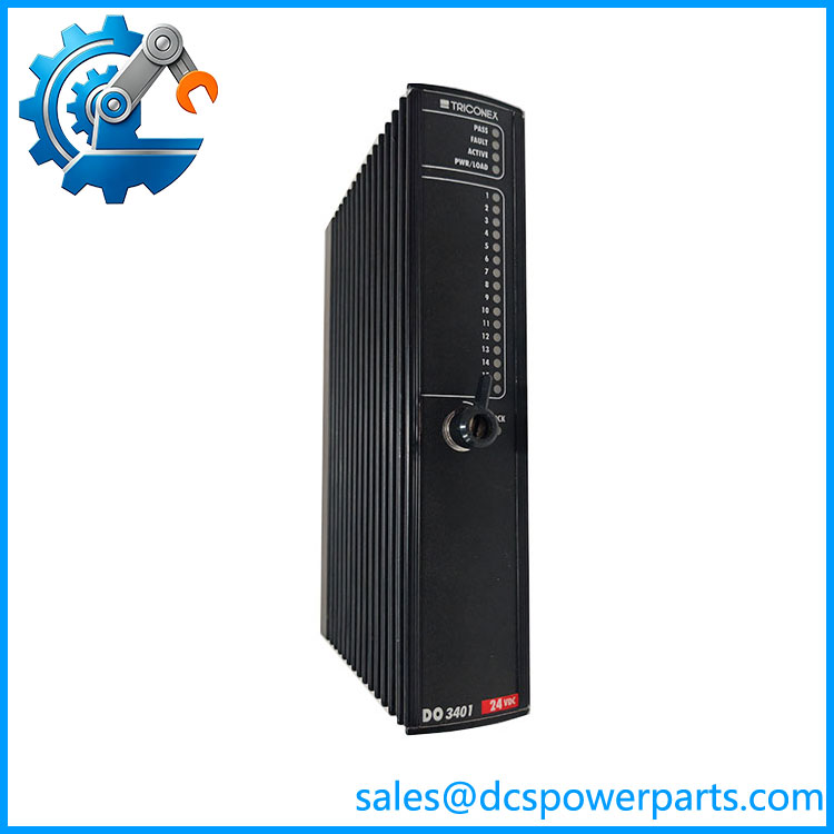
TRICONEX DO3401
Key Features and Advantages
Voting in hardware, not software: the Quad Voter passes power only when two of three channels close their switches, through parallel-series paths that are redundant against both stuck-on and stuck-open failures. A software vote cannot deliver that, because the failure being defended against is the output stage itself.
Sixteen points chosen for load duty: half the count of the input cards, in the same 44 mm front. Planning point counts on this platform has to account for that asymmetry — an output-heavy unit needs twice the positions, and the 14-module ceiling is where that becomes visible.
Current specified in two regimes: 3.0 A typical when healthy, and still 0.7 A minimum / 1.5 A typical when a channel leg is lost. Degraded operation is designed in, so a failed channel is a maintenance item rather than an immediate trip.
Stuck-on detection in under half a second: the OVD routine finds a point that will not release, which is the failure mode that keeps a shutdown valve open. Detection time, not detection principle, is what a proof-test interval is built on.
Diagnostic glitch published honestly: under 2 ms maximum, about 500 µs typical. Fine for solenoids and coils; not fine for a microsecond-responding load, and knowing which one is on a terminal strip prevents a commissioning argument.
Loop-back that reads the real terminal: the module checks the point against the off, transition and on threshold bands and scans all sixteen in under a millisecond, so loss of field power and a point shorted on or off are field alarms rather than mysteries.
Low leakage and a specified drop: under 1 mA off-state leakage keeps a de-energised circuit genuinely de-energised, and the under 1.0 VDC drop at 1.5 A tells you both what the load actually receives and how much heat the position will produce.
Carrier as policy: standard limiting on the 2401, a 180 Ω series resistor per point on the 2401L, high-voltage on the 5402 carrier. The same module, three different field behaviours, decided by what it is plugged into.
Honest limits: no dry contacts, no mains switching, no per-point isolation, a diagnostic that momentarily disturbs the output, and a point count that will not match the input side of the same baseplate family.
Applications
Emergency shutdown valve solenoids: the primary duty of this card — holding pilot solenoids energised and releasing them on trip, where a stuck-on output is the failure that matters and the OVD’s half-second detection is the reason the module is acceptable for the loop.
Burner management valve trains: fuel, pilot and purge valve positions, on positions where the load is a 24 VDC solenoid and the load’s own suppression handles the switch-off transient.
Compressor and turbine package trips: trip outputs to the local panel, permissives into starter control, and cooling or lube-oil demand signals, all at control-level voltage with interposing relays absorbing coil energy.
Motor control centre interfaces: high-side signals into intelligent starters and protection relays, with the safety layer switching ahead of the process control layer and the starter’s input block presenting a benign, resistive load.
Pipeline and terminal valve actuation: block-and-bleed and motor-operated valve control interfaces on remote sites, where the 15 to 30 VDC operational window tolerates supply variation along a long 24 VDC distribution.
Where the load is not a good fit: annunciator panels and other devices incompatible with a high-side solid-state switch belong on the 3451 relay module, and mains-potential loads belong on the high-voltage carrier route. Recognising both boundaries early avoids a card that works on the bench and misbehaves in the panel.
Legacy Trident columns under spares management: replacing a 3401 on a 7400209-030 carrier, where the module changes and the field wiring does not — and where the fitted carrier’s current policy must be confirmed before a replacement is ordered.
Related Products
2401 Digital Output Baseplate Kit (7400209-030) — the standard carrier, assembly 3000659-130; supplies field terminals and the shared return, sold with this module as the 5401 TriPak. 2401L Digital Output Baseplate Kit (low current) — the same function with a 180 Ω series resistor per output, for loads that need integral current limiting; packaged as the 5401L TriPak. 5402 High-Voltage Digital Output TriPak — this module on the high-voltage carrier, for field devices at mains potential. 3451 Solid-State Relay Output Module with 2451 SRO Baseplate — 32 relay outputs, commoned in pairs, 0.5 A per channel, 0.75 A fuses on the baseplate; the answer for annunciators and loads a high-side switch cannot drive. 3301 Digital Input Module with 2301 Baseplate — the input counterpart, 32 points, the same 44 mm front and half the current per point. 3361 Analog Input/Digital Input Module with 2361 Baseplate (7400210-020) — mixed input position, for cabinets that need both classes in one slot. 3481 Analog Output Module with 2481 Analog Output Baseplate Kit — 4–20 mA control outputs, a different circuit entirely; not interchangeable with a discrete output position. 2921 I/O Interconnect Assembly and 2281 I/O Bus Extender Module Kit — column link, and the extender for runs beyond eight baseplates or 200 m.
Installation and Maintenance
Before installation: confirm the label reads DO3401 and the carrier is the one the position was built with — 7400209-030 standard, the low-current carrier if the load depends on its 180 Ω series resistor, or the high-voltage carrier where the field device runs at mains potential. Establish each load’s inrush against the module’s switching regime and its holding current against the on-state drop at 1.5 A, and confirm that no device on the position responds faster than the diagnostic glitch can be tolerated. Fit suppression at every inductive load, at the coil, before first energisation.
Installation: seat the module on a terminated carrier, engage the lock lever, and bring the column up. Prove each point at the field device — command it, confirm the device moves, confirm the loop-back agrees — and check the sixteen points against the wiring schedule rather than assuming the numbering matches the drawing. Verify field power at the terminals under load, not open-circuit, because a supply that reads 24 VDC at rest and 19 VDC with sixteen solenoids pulled is the classic reason a rebuilt panel drops outputs on the first trip.
Maintenance: a Fault indication is a channel fault, not a dead card, and the module is specified to keep operating through a single fault — so diagnose before replacing. Work outward from the terminal when an output does not operate: coil continuity, suppression component, fuse, field supply, return. When several points fail together, suspect the shared return or the field supply rather than sixteen switches. Keep the terminal covers fitted, inspect for heat discolouration around high-current terminations, and record both the module revision and the carrier variant in the as-built file. On proof tests, verify release as carefully as operation: a valve that trips but will not reset is a fault the diagnostics were never designed to see.
Warranty and Quality
Every DO3401 is supplied as the Triconex Model 3401 Digital Output Module — 16 commoned high-side outputs, 24 VDC nominal with a 15–30 VDC operational window, Quad Voter output paths, self-limiting switching at 4.8 A with 3.0 A typical, degraded operation at a 0.7 A floor, OVD stuck-on and stuck-off detection within 500 ms, loop-back across all sixteen points — and identity is confirmed by label and revision before dispatch, because this number is routinely listed online with 32 points, described as a relay card, and quoted with current figures that belong to no Triconex product. Each unit is inspected for housing and front-panel condition, connector and lock-lever integrity, keying, indicator operation, and evidence of prior repair, heat damage or arc damage at the output terminations. Where a Trident bench is available, the module is seated on a 7400209-030 carrier and exercised into resistive and inductive loads at rated current: switching and release at each point, on-state drop measured under load, off-state leakage verified, loop-back thresholds checked at the terminals, OVD behaviour observed for diagnostic glitch and stuck-state detection, and active/hot-spare transfer confirmed. A 12-month repair, replacement or refund commitment applies. Technical support covers what this card actually raises: explaining why a 3401 position is sixteen points and not thirty-two, selecting between the standard, low-current and high-voltage carriers, matching load inrush to the two current regimes, judging whether a given device tolerates the OVD glitch, and recognising when the load belongs on the 3451 relay module instead.
免费
今天 11:39