Description
Product Overview
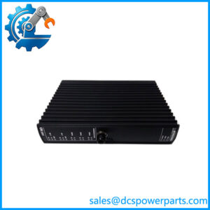
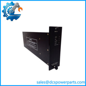
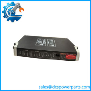
DI3361 is Model 3361, the mixed input module of the Trident safety controller: thirty-two channels on a single card, the first sixteen discrete and the last sixteen analogue. The point map is fixed in the hardware — discrete points are 1 to 16, analogue points 17 to 32 — and that is the fact that shapes everything else about this module. It means the cabinet’s wiring schedule is decided the moment a 3361 is chosen for a position: the field terminations for switches and the field terminations for transmitters occupy defined halves of the carrier, and no configuration or software setting moves a point from one half to the other.
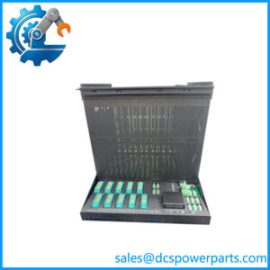
The card is the module half of a two-part arrangement. Its carrier, the Model 2361 baseplate (7400210-020), holds the terminals and supplies the field-side loading: roughly 3 kΩ for each discrete point and a 250 Ω current-sense burden for each analogue point. The module itself adds what the carrier cannot — a 100 Ω, 0.01% current-to-voltage resistor and a 12-bit conversion chain on the analogue side, a three-channel scanning architecture on the discrete side, and the diagnostic machinery that keeps both halves honest. Understanding that division matters at the purchasing counter as much as at commissioning, because the burden values quoted in the specification are the carrier’s, and the accuracy figures are the module’s.
Analogue behaviour follows the platform’s current-input convention rather than a general-purpose front end: 4 to 20 mA nominal, read below and above the nominal span, 33 VDC absolute maximum on the input, 50 mA current limit, and an input update of 16 Hz. Conversion is 12-bit with 0.15% of full-scale accuracy, and the analogue-to-digital converter scans all thirty-two points in under a millisecond — so the 16 Hz figure describes the declared measurement rate, not a bottleneck in the scan. Sixteen hertz is deliberate: it is fast enough for pressure, level, flow and valve-position loops in a safety application, and slow enough that electrical noise on a field cable is filtered rather than faithfully digitised as a trip.
The discrete half behaves like the dedicated input module but with one number changed. Nominal 24 VDC, operational 15 to 30 VDC, 33 VDC absolute maximum, −0.6 VDC reverse, thresholds at 0 to 5 VDC off, 6 to 14 VDC transition, 15 to 30 VDC on, input delay under 10 ms, and impedance published as more than 100 kΩ without the baseplate against about 3 kΩ with it. That higher no-carrier figure tells you the discrete half here is a lighter front end than the 3301’s, and that on this card the carrier is doing more of the electrical work — which is precisely why the mixed module and the mixed carrier are ordered and replaced as a matched pair.
Diagnostics on both halves use the platform’s forced-value approach. The analogue channels are tested by injecting a known value into the measurement chain and confirming the result; the discrete channels are forced with a test voltage around 36% of nominal for under 2 ms per test, held inside the 0 to 5 VDC region so a test cannot be mistaken for a real closure. The published consequence is a diagnostic coverage that holds only up to a maximum toggle rate of about 20 transitions per second: push a discrete point faster than that and the forced-value test no longer fits between the real edges. This is not a defect — it is the boundary of the technique, and it is the single most useful thing to know when deciding whether a fast-pulsing signal belongs on this card or on the pulse input module.
Isolation follows the platform: functional earth to protective earth 500 VDC minimum, and between functional earths for logic 800 VDC minimum. Points are commoned rather than individually isolated, so the module suits switches and transmitters fed from a common isolated field supply, not floating sources. The card is mechanically keyed, capable of hot spare in an I/O set, and draws its logic power from the MP baseplate at 24 VDC (19.2 to 30 VDC) — the field-side load is carried at the terminals.
The packaged form is the 5361 TriPak, one module with one 2361 baseplate — and Model 2361 is not Model 2351: the two ordering numbers differ by one digit, which is the most common wrong shipment in this family.
Reseller pages get this number wrong in both directions. DI3361 is sold as a plain digital input module, which omits half its function, and it is confused with DI3301, which is a different card on a different carrier with a different discrete front end. The distinctions that matter are the point split, the carrier, and the toggle-rate limit — none of which appear in a marketplace listing.
Technical Specifications
| Parameter | Value |
|---|---|
| Model and platform | DI3361 — Triconex Model 3361 Analog Input/Digital Input Module; Trident (Trident v2) TMR safety controller |
| Module type | Mixed input; 32 points commoned; three isolated channels, one ASIC per channel; hot spare capable, mechanically keyed |
| Point map | Discrete points 1–16; analogue points 17–32; fixed in hardware, not configurable |
| Analogue input | 4–20 mA nominal, readable below and above span; 33 VDC absolute maximum; 50 mA limit; input bandwidth / update 16 Hz |
| Analogue conversion | 12-bit; accuracy 0.15% of full scale; 100 Ω, 0.01% current-to-voltage resistor; all 32 points scanned in < 1 ms |
| Analogue burden | 250 Ω with baseplate |
| Discrete input | 24 VDC nominal; operational 15–30 VDC; absolute maximum 33 VDC; reverse −0.6 VDC |
| Discrete thresholds and delay | 0–5 VDC off; 6–14 VDC transition; 15–30 VDC on; input delay < 10 ms |
| Discrete impedance and loading | > 100 kΩ without baseplate; approximately 3 kΩ with baseplate; 0.2 W per point at 24 VDC, 0.5 W at 33 VDC |
| Diagnostics | Forced-value diagnostics on both halves; discrete test at ~36% of nominal for < 2 ms per test, held within the 0–5 VDC off region; diagnostic coverage maintained only below ~20 transitions per second |
| Isolation and logic power | FE-to-PE 500 VDC min; FE-to-FE (logic) 800 VDC min; logic power 24 VDC (19.2–30 VDC) from MP baseplate, < 3 W |
| Carrier and packaging | Model 2361 AI/DI baseplate (7400210-020), 178 × 249 mm; 5361 TriPak (3361 + 2361); module 44 × 220 × 169 mm; 70 °C maximum ambient |
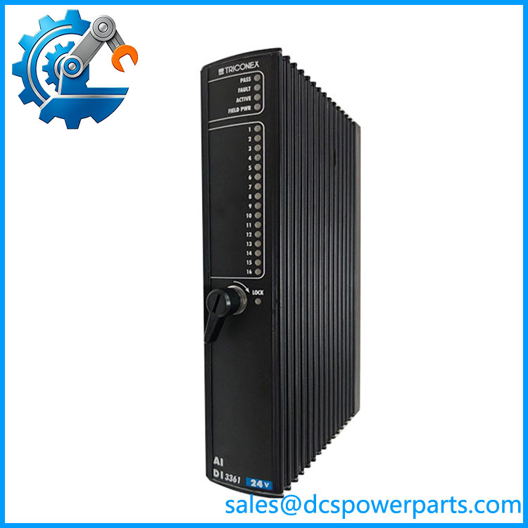
TRICONEX DI3361
Key Features and Advantages
Two electrical worlds on one position: sixteen discrete and sixteen analogue channels in one slot, so a vessel or a compressor package that needs four pressure transmitters, two flow loops and ten switches does not consume three I/O positions to do it. On a platform capped at fourteen I/O modules, that economy is not cosmetic.
A fixed point map that removes ambiguity at the terminal: discrete 1 to 16, analogue 17 to 32, decided by hardware. Wiring schedules stay valid across a module replacement, and there is no configuration step in which a transmitter can be mistaken for a switch.
Analogue accuracy stated plainly: 12-bit conversion, 0.15% of full scale, a 100 Ω 0.01% sense resistor doing the current-to-voltage work. That is an accuracy class appropriate to a trip threshold with margin, and the figure covers the module rather than an idealised bench condition.
A scan that is faster than the declared rate: the converter walks all thirty-two points in under a millisecond while the measurement update is 16 Hz. The filtering is deliberate — noise on a field cable is averaged rather than sampled as a transient, which is how an analogue input avoids becoming a nuisance trip source.
Forced-value diagnostics on both halves: injected test values prove the analogue chain can still measure, and a 36% test voltage held inside the off region proves the discrete chain can still see without ever looking like a real closure.
The toggle-rate boundary stated instead of hidden: diagnostic coverage holds below about 20 transitions per second. For switches and limits that is generous; for a fast counter input it is the reason to use the pulse module. Publishing the limit means a fast signal is a design decision rather than a commissioning discovery.
Commoned points and a matched carrier: about 3 kΩ on the discrete half and 250 Ω on the analogue half both come from the baseplate, so the module and the 7400210-020 carrier are a set. Replacing one without the other changes the electrical behaviour of every point on the position.
Honest limits: no outputs, no per-point isolation, no discrete bandwidth beyond 25 Hz-class filtering, and discrete accuracy that depends on a carrier the module does not include. It is a mixed input card, and its value comes from being matched properly rather than from covering everything.
Applications
Wellhead and test separator packages: flowing pressure, temperature and differential pressure transmitters on the analogue half, valve-position and pressure switches on the discrete half, in a single position where the point count per skid is small and the cabinet real estate is fixed.
Compressor and pump auxiliary monitoring: suction and discharge pressures, lube-oil pressure and temperature on channels 17 to 32, with run-status, vibration trip contacts and permissives on channels 1 to 16 — a package that reads naturally as half measurement and half switch.
Burner and furnace supervision: analogue channels for flame-signal conditioning and fuel pressure, discrete channels for purge, low-fire and valve-proven contacts, on positions where the two classes arrive together at the marshalling.
Tank farm and terminal control: level transmitters and overfill switches in the same cabinet column, with the fixed point map keeping the overfill circuit distinguishable from the measurement circuit at the terminal strip.
Small skids and remote well sites: where a fourteen-position controller must serve several packages, mixed modules conserve positions that would otherwise be spent on separate cards for four loops and ten switches.
Legacy Trident columns under spares management: replacing a 3361 in a position built around 7400210-020, where the carrier stays and only the module changes — and where ordering 7400210-010 instead of -020 is the error to guard against.
Where it does not belong: high-rate counting, turbine speed pickups and fast pulse trains, which exceed the discrete half’s diagnostic toggle rate and belong on the pulse input module.
Related Products
7400210-020 Model 2361 AI/DI Baseplate Kit — the matched carrier supplying 250 Ω analogue burdens and ~3 kΩ discrete loading; the 5361 TriPak pairs it with this module. 5361 TriPak — packaged one-module-plus-one-baseplate combination for the mixed input function. 7400210-010 Model 2351 Analog Input Baseplate Kit — the one-digit-near neighbour for pure analogue positions; not interchangeable with the mixed carrier. DI3301 — Model 3301 Digital Input Module — dedicated 32-point discrete card on carrier 2301, the right choice when a position needs only switches and more of them. AI3351 — Model 3351 Analog Input Module — dedicated 32-point analogue card, when a position is entirely measurement. 3401 Digital Output Module with 2401 Digital Output Baseplate Kit — the output counterpart for a position that must drive solenoids as well as read inputs. 3381 Pulse Input Module — the destination for signals faster than the mixed card’s discrete diagnostic toggle rate. 2921 I/O Interconnect Assembly — passive link carrying I/O messages and logic power between baseplates in a column.
Installation and Maintenance
Before installation: confirm the label reads DI3361 and not DI3301, and confirm the carrier in the position is 7400210-020 and not the visually identical 7400210-010, because the analogue burden and discrete loading both live there. Check keying and lock-lever condition, verify that the wiring schedule respects the fixed map — discrete 1 to 16, analogue 17 to 32 — and confirm the field supply can carry sixteen discrete points at 0.2 W each alongside the transmitters’ loop current. Confirm no discrete channel needs to toggle faster than about twenty times per second; if one does, the position is planned wrong rather than the card.
Installation: seat the module on a terminated carrier, engage the lock lever, and bring the column up. Prove the discrete half at the field device, one point at a time, and prove the analogue half with a loop calibrator at 4, 12 and 20 mA, recording the readings against the declared span; a channel that misses 0.15% full scale at 20 mA is a loop problem to be solved before the loop is placed in service. Keep covers on unused positions and record the module revision together with the carrier’s ordering variant in the as-built file.
Maintenance: treat a failed discrete point and a failed analogue point as different diagnoses. A discrete channel that reads stuck is a contact, a fuse or a termination; an analogue channel drifting at the top of its span is usually wiring resistance or loop supply, and the 250 Ω burden in the carrier is the reference to measure against. When several channels on one half misbehave together, suspect the carrier’s shared return and terminal block before the card. Replace the module and leave the carrier if the fault follows the card; replace nothing until the loop has been measured. Keep one spare module rather than a spare carrier, and on each proof test confirm the forced-value diagnostics still complete — the coverage figure is what an audit asks for, and it depends on the toggle rate the application actually applies.
Warranty and Quality
Every DI3361 is supplied as the Triconex Model 3361 Analog Input/Digital Input Module — 32 commoned points with a fixed map of 16 discrete and 16 analogue, 4–20 mA inputs at 12-bit and 0.15% full scale, discrete thresholds at 0–5 / 6–14 / 15–30 VDC, forced-value diagnostics on both halves — and identity is confirmed by label and revision before dispatch, because this number is sold online as a plain digital input module, is confused with the dedicated DI3301, and is paired in the field with a carrier one digit away from its sibling. Each unit is inspected for housing and front-panel condition, connector and lock-lever integrity, keying, indicator operation, and evidence of prior repair or moisture ingress. Where a Trident bench is available, the module is seated on a 7400210-020 carrier, discrete points are driven through the off, transition and on regions at the field terminals, analogue points are exercised with a calibrated current source across the span and checked against the 0.15% full-scale figure, the 32-point scan is verified, forced-value diagnostics are exercised on both halves, and active/hot-spare transfer is confirmed. A 12-month repair, replacement or refund commitment applies. Technical support covers what this card actually raises: keeping the 3361 module distinct from the 2301/3301 discrete pair and from the 2351 analogue carrier, reading the fixed point map into a wiring schedule, accounting for carrier-supplied 250 Ω and ~3 kΩ burdens, and judging when a signal’s toggle rate puts it beyond this card’s diagnostic coverage and onto the pulse input module.