Description
Product Overview
DO2401 7400209-030 is the output carrier of the Trident safety controller: Model 2401, a baseplate that takes one Model 3401 Digital Output Module and terminates thirty-two discrete output points. It has to be understood as the opposite end of the platform from the input carriers, and not only in the obvious direction. On an input position, the carrier’s job is to shape what the field circuit looks like to the module — the ~3 kΩ loading that makes a contact legible. On an output position, the carrier’s job is to carry the current the module switches, out to a terminal, into a solenoid, a pilot valve, a relay coil or a motor-starter interlock, and back along a shared return. The electrical duty is transferred from signal to load, and that changes what to look at when a position misbehaves.
Model 2401 sits on the standard 178 × 249 mm I/O footprint and is the smaller sibling of the wide carriers, which matters when planning a column: output positions consume the same slot as input positions but bring with them field wiring that has to leave the cabinet, and the terminal block is the boundary. The kit is complete in the same way the input kits are — the baseplate, the I/O interconnect assembly 2921 that carries I/O messages and logic power along the column, the slot cover 2900 and the terminal cover 2901. Those two covers are more consequential on an output position than on an input one: a live terminal block left open in a cabinet is an exposure as well as a corrosion site.
The output circuit itself is a 24 VDC arrangement: nominal 24 VDC, operational 15 to 30 VDC, 33 VDC maximum. That places the carrier firmly in the low-voltage control world — pilot solenoids, interposing relays, solid-state input blocks on motor starters, annunciator circuits. It is not a carrier for switching 120 or 230 VAC loads, and the platform answers that need with a separate high-voltage output route rather than by stretching this one. The per-point and per-module current rating belongs to the module documentation rather than to the carrier, and the existence of a low-current output variant in the same family is the practical proof that the question “how much current can a point carry” has more than one answer. A buyer should establish the rating for the module actually fitted, and should treat the carrier’s contribution as the terminals, the return path and the integrity of the connection.
The switching element is solid-state, which is a different animal from a relay card. There are no contacts to weld, no coil to age, and no mechanical life to count — but there is also no inherent isolation between the output circuit and whatever the field device does with it, and no tolerance for an inductive load’s collapse voltage unless the field side deals with it. Solenoid valves and relay coils generate a reverse transient at switch-off; on a solid-state output position that transient is managed at the load, with suppression fitted at the coil, not assumed to be absorbed somewhere inside the card. This is the single most useful installation habit on an output position, and it is also the most common omission found during commissioning of a rebuilt panel.
Diagnostics on the output side work on the same principle as the rest of the platform: the module tests the driver rather than trusting the commanded state, and reports a fault at the point. What diagnostics cannot see is downstream of the terminal — a coil that has gone open, a solenoid that has stuck, a fuse that has blown in a marshalling panel. Output positions fail in the field far more often than in the card, and a maintenance routine built around that expectation saves module replacements that were never needed.
The packaged form is the 5401 Digital Output TriPak, one Model 3401 module with one Model 2401 baseplate. Two related routes exist for positions this carrier does not serve: the low-current output variant in the same family, where the load is a solid-state input rather than a coil, and the high-voltage output arrangement where the field device genuinely runs at mains potential. For hazardous-area installations, the DO carrier is also built in a hazardous-location version, 7400219-030 (Model 2401H), which is a different article with a different certification path.
Marketplace listings blur this number in a predictable way: the ordering number is offered as if it were the module, channel counts appear that do not match thirty-two, and it is sometimes described as a relay output card. None of those readings survives contact with a terminal schedule. The carrier is a carrier; the module is 3401; the points are thirty-two and commoned; and the return is shared, which means a fault in the return wiring presents as many failed outputs rather than one.
Technical Specifications
| Parameter | Value |
|---|---|
| Model and identity | DO2401 = Trident Model 2401 Digital Output Baseplate Kit; ordering number 7400209-030; baseplate assembly number 3000659-130 |
| Manufacturer / platform | Triconex, Invensys; now Schneider Electric — Trident (Trident v2) TMR safety controller |
| Item class | Digital output baseplate kit — passive carrier with field terminals and output current path |
| Points and module | 32 points, commoned shared return; accepts one Model 3401 Digital Output Module per slot; two slots per carrier (active / hot spare) |
| Output circuit | 24 VDC nominal; operational 15–30 VDC; 33 VDC absolute maximum |
| Switching element | Solid-state output driver in the module; carrier supplies terminals and return path |
| Current rating | Per-point and per-module limits are defined by the fitted output module; a low-current variant exists in the same family for light loads |
| Diagnostics | Point-level driver verification and fault reporting at the module; field devices, coils and fuses downstream are not covered |
| Kit contents | I/O baseplate; I/O interconnect assembly 2921; slot cover 2900; terminal cover 2901 |
| Terminals and dimensions | Compression terminals 24–12 AWG (0.2–3.3 mm²); baseplate 178 × 249 mm; module 44 × 220 × 169 mm; 70 °C maximum ambient |
| Isolation and logic power | FE-to-PE 500 VDC min; FE-to-FE (logic) 800 VDC min; logic power 24 VDC (19.2–30 VDC) from MP baseplate, < 3 W per I/O module |
| Related variants and packaging | 5401 Digital Output TriPak (3401 + 2401); low-current output TriPak 5401L; high-voltage output route 5402; hazardous-location carrier 7400219-030 (Model 2401H) |
| System capacity | Up to 14 I/O modules per controller, reduced to 10 when AO or PI modules are present |
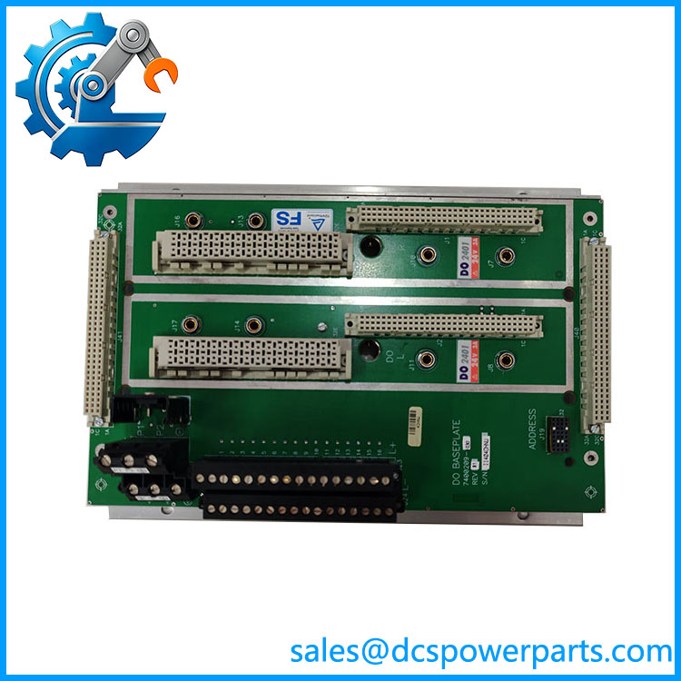
TRICONEX DO2401 7400209-030
Key Features and Advantages
Thirty-two points on one position: a single carrier closes out an ESD valve set, a burner valve train and its permissives, or a bank of interposing relays without spending three I/O slots on the platform’s fourteen. Position economy is a real constraint here, not a convenience.
A 24 VDC output circuit with margin above nominal: operational to 30 VDC and tolerant to 33 VDC, so a field supply that runs a little high does not put the driver outside its window. The circuit is honest about what it drives — pilot solenoids, relays, starter interlocks — and does not pretend to be a mains switching position.
Carrier as current path, not decoration: the terminals and the common return carry the summed load of every energised point. Sizing the field supply and checking the return conductor are the two calculations that decide whether a rebuilt panel works on the first attempt.
Solid-state switching with no mechanical life to count: no contact welding, no coil ageing, no bounce on pick-up. What replaces those failure modes is transient management at the load — and the discipline of fitting suppression at every coil is worth more than any claimed endurance figure.
Point-level driver verification: the module tests what it switches rather than reporting what it was told to do. A driver that has failed is a reported fault instead of a silent loss of a trip path.
Complete kit with the protection items: interconnect 2921, slot cover 2900 and terminal cover 2901 arrive with the baseplate. On a live output position an uncovered terminal block is both a corrosion site and a safety exposure, and covers left in a stores bin are covers that were never needed until an inspection.
Clear variant boundaries: the same family provides a low-current output for solid-state loads and a high-voltage route for mains devices, and hazardous areas have their own carrier. Choosing wrongly is visible immediately, which is better than discovering it at first energisation.
Honest limits: commoned returns, no per-point isolation, no field-device diagnostics, and a current rating owned by the module rather than the carrier. The carrier’s contribution is connection integrity and return capacity — and that is exactly what to inspect when outputs behave strangely.
Applications
Emergency shutdown valve actuation: pilot solenoids on shutdown valves, driven from trip logic, where thirty-two points close out a unit’s valve set and the shared return is planned as a single conductor run back to the cabinet earth reference.
Burner management valve trains: fuel and pilot valves, purge and low-fire positions, and permissives to the flame programmer, on positions where the load is a 24 VDC solenoid and the suppression is fitted at the coil.
Compressor and pump package interlocks: permissive outputs to starter control, lube-oil and cooling demand signals, and trip outputs to local panels — circuits where an interposing relay absorbs the coil energy and protects the output driver.
Alarm and annunciation circuits: solid-state input blocks on annunciator panels and distributed I/O heads, the case where the low-current output variant is the better match and the standard rating would be wasted headroom.
Motor control centre interfaces: 24 VDC control-level signals into intelligent starters and protection relays, with the output position acting as the safety layer ahead of the process control layer.
Water and wastewater plants: pump start permissives, penstock and valve control, and remote indication outputs across a site where field runs are long and the return conductor is often the weakest link in the design.
Hazardous-area installations: the 7400219-030 (Model 2401H) carrier where the position itself is in a classified location — a different article with its own certification, not this one with a different label.
Where it must not be used: switching mains-potential loads, driving devices whose inrush exceeds the fitted module’s rating, or serving as a dry-contact interface. Each of those has a proper route elsewhere in the family, and none of them is this carrier.
Related Products
3401 Digital Output Module — the module this carrier serves; 32 commoned solid-state outputs, point-level driver diagnostics; sold with it as the 5401 Digital Output TriPak. 5401 Digital Output TriPak — packaged one-module-plus-one-baseplate combination, the standard ordering route. 3401L / 5401L Low-Current Digital Output — reduced-current variant in the same family for solid-state and light loads. 5402 High-Voltage Digital Output — the separate route for mains-potential field devices; not interchangeable with a 24 VDC output position. 7400219-030 Model 2401H Digital Output Baseplate Kit — hazardous-location version of this carrier, with its own certification path. 2301 Digital Input Baseplate Kit (7400208B-020 / 7400208C-020) — the input carrier on the same footprint; terminals and wiring must never be mixed between the two. 3401 DO Module with 2481 Analog Output Baseplate Kit — note that analogue output positions use a different carrier entirely; the 2481 is not a 2401. 2921 I/O Interconnect Assembly and 2281 I/O Bus Extender Module Kit — the column link and the extender kit for runs beyond eight baseplates or 200 m.
Installation and Maintenance
Before installation: confirm the label reads DO2401 7400209-030 and not 7400219-030, which is the hazardous-location carrier and a different article. Confirm the position carries a 3401 module and that its current rating suits the load — a solenoid’s inrush is not its holding current. Verify the kit for interconnect 2921, slot cover 2900 and terminal cover 2901, check keying, and establish that the field supply feeding the output circuit can carry the sum of the energised points plus margin, with a return conductor sized for the same current.
Installation: mount on the 178 mm footprint, land field conductors at 24 to 12 AWG with ferrules where required, and fit suppression at every inductive load — a diode across a DC solenoid coil, at the coil, not at the cabinet terminal. Keep output wiring separated from analogue and input cabling in the duct, and never borrow the return path of another position. Seat the module, engage the lock lever, and prove each output at the field device: energise from TriStation, confirm the device moves, then confirm the module reports the state it actually drove. Record the module revision and the fitted variant in the as-built file.
Maintenance: when an output fails to operate, work outward from the terminal — coil continuity, suppression component, marshalling fuse, field supply — before condemning the card, because the driver is the least likely element in the chain. When several outputs on one position fail together, suspect the shared return or the field supply rather than thirty-two drivers. Keep terminal and slot covers fitted, inspect terminal blocks on planned outages for loosened strands and heat discolouration, and keep a spare module rather than a spare carrier. On proof tests, verify that each output both operates and releases, and that the field device returns — a valve that trips but does not reset is a fault the driver diagnostics will never report.
Warranty and Quality
Every DO2401 7400209-030 is supplied as the Trident Model 2401 Digital Output Baseplate Kit — baseplate assembly 3000659-130 with interconnect 2921, slot cover 2900 and terminal cover 2901 — and its identity is confirmed by printed ordering number and baseplate assembly marking before dispatch, because the number is sold online as if it were a module, quoted with channel counts that do not match thirty-two, sometimes described as a relay card, and sits one digit-family away from the hazardous-location carrier 7400219-030. Each unit is inspected for terminal-block condition, connector and interconnect seating, return-path integrity, corrosion, cover completeness, keying and evidence of prior re-termination. Where a Trident bench is available, the carrier is populated with a Model 3401 module pair, powered through the column interconnect, and outputs are exercised into a resistive and an inductive load bank at the module’s rated current, checked for correct operation and release, for point-level fault reporting, for clean active/hot-spare transfer, and for behaviour with suppression fitted and removed at the coil. A 12-month repair, replacement or refund commitment applies. Technical support covers what this carrier actually raises: separating 2401 from 2401H and from the analogue 2481, establishing the fitted module’s current rating instead of assuming the carrier defines it, sizing a field supply and return conductor for a fully energised position, and setting suppression practice for inductive loads on solid-state outputs.