Description
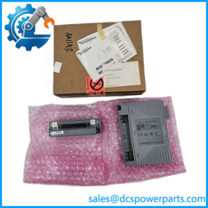
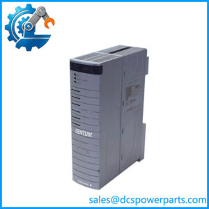
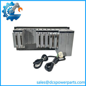
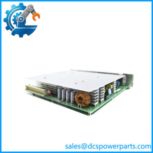
YOKOGAWA AER4D-05
Product Introduction
The Yokogawa AER4D-05 is a 16-point RTD terminal board used with Yokogawa field input/output hardware. Yokogawa’s terminal-board specifications identify the AER4D family specifically for resistance temperature detectors, with 16 RTD points and M4 screw terminals. The documented associated I/O module is AAR145, with the AKB335 cable used for the connection between the terminal board and the FIO system.
The Yokogawa AER4D-05 is therefore not an analog input module in the conventional sense. The actual signal conversion and processing are performed by the associated FIO input hardware; AER4D-05 provides the physical field termination and signal routing interface. This distinction is important when troubleshooting a temperature channel. Replacing the terminal board will not correct a failed RTD input circuit inside the AAR145 module, and replacing the I/O module will not necessarily resolve a damaged terminal, loose connection, or field-wiring problem on the AER4D-05.
The Yokogawa -05 is also useful as a maintenance replacement for existing Yokogawa installations because its mechanical and electrical interface is tied to the FIO architecture. Available documentation l among Yokogawa terminal boards and distinguishes it from AEA4D analog terminal boards and AET4D thermocouple terminal boards.
Technical Specifications
| Parameter | Specification |
|---|---|
| Product Model | |
| Manufacturer | Yokogawa |
| Product Type | RTD terminal board |
| System | Yokogawa FIO / CENTUM VP |
| Signal Type | Resistance Temperature Detector (RTD) |
| Number of Points | 16 |
| Terminal Type | M4 screw terminals |
| Associated I/O Module | AAR145 |
| Connection Cable | AKB335 |
| Installation Function | Field signal termination and routing |
| Insulation Resistance | ≥100 MΩ at 500 VDC* |
| Dielectric Strength | 500 VAC for 1 minute* |
| Operating Temperature | -40°C to +85°C* |
| Approx. Weight | 1.5 kg |
| Dimensions | Approx. 482.6 × 88.1 × 53 mm* |
| Communication Protocol | None; passive signal termination interface |
| Power Supply | No independent control-system power function |
| Protection Rating | Verify for the installed cabinet/application |
*These environmental and mechanical figures are reported by avail product references; the Yokogawa FIO specification should take precedence for a project-specific installation.
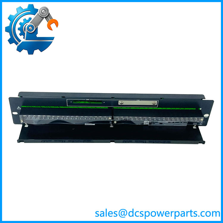
YOKOGAWA AER4D-05
Main Features and Engineering Considerations
16-Point RTD Interface
The principal purpos is to terminate 16 RTD signal points. Yokogawa documentation categorizes specifically for resistance temperature detectors and lists AAR145 as the connected module.
This makes the board suitable for temperature measurements from process equipment such as vessels, heat exchangers, compressors, pumps, furnaces, and other rotating or static plant equipment where RTDs are used.
Direct Field Termination
The board uses M4 screw terminals, giving maintenance personnel direct access to the field wiring. Correct terminal identification and tightening are important because RTD measurements are sensitive to wiring resistance and connection quality.
For three-wire or four-wire RTDs, the exact terminal assignment must follow the Yokogawa wiring diagram for the associated AAR145 configuration. Do not assume that all RTD wiring arrangements can be landed identically.
Is Not the Measurement Electronics
This is the most important engineering distinction.
is a terminal board, not the RTD measurement converter itself. The associated AAR145 FIO module performs the input acquisition and processing. Yokogawa’s terminal-board table explicitly associates with and AKB335.
When diagnosing a failed temperature channel, check the complete signal path:
RTD → field wiri → AKB335 → → Yokogawa control system
A fault can exist at any point in this chain.
Cable Compatibility
The documented connection cable is AKB335. A replace should therefore be checked against the cable already installed in the cabinet. Connector compatibility should never be inferred solely from physical appearance.
Distinguishing RTD From Thermocouple Boards
Yokogawa’s terminal-board family contains several visually related products. is designated for RTDs, while AET4D is used for thermocouple signals. AEA4D is associated with general analog signals.
This distinction matters during procurement because these boards are not interchangeable simply because they occupy similar cabinet positions.
Maintenance Considerations
For a replacement board, inspect the screw terminals for discoloration, stripped threads, corrosion, loose conductors, and evidence of overheating. Verify cable identification against the system drawings before removing the existing board.
If the plant has redundant FIO architecture, also confirm whether the terminal arrangement corresponds to the single or redundant configuration used by the installed system.
Application Scenarios
- Process temperature measurement
- RTD field signal termination
- Yokogawa CENTUM VP installations
- FIO-based temperature monitoring
- Refinery and petrochemical plants
- Chemical processing facilities
- Power generation plants
- Oil and gas process facilities
- Heat exchanger temperature monitoring
- Compressor and pump temperature monitoring
- Legacy Yokogawa control-system maintenance
Engineer’s Guide: Field Pitfalls
1. Do not an RTD input module.
It is a terminal board. The associated module performs the input acquisition function.
2. Verify the RTD wiring method.
Three-wire and four-wire RTD installations have different connection requirements. Follow the Yokogawa wiring diagram for the installed system.
3. Check the cable.
is documented with the AKB335 connection cable. Verify connector and cable compatibility before replacement.
4. Do not substitute an AET4D.
AET4D is intended for thermocouple signals, while is the RTD terminal-board family.
5. Inspect the field terminals.
Loose RTD connections can produce unstable or biased temperature readings even when the input module is operating normally.
6. Check the complete signal chain.
If a temperature point is reading incorrectly, measure the RTD itself and verify field wiring before concluding or has failed.
Frequently Asked Questions
What is Yoko?
It is a 16-point RTD terminal board for Yokogawa FIO systems, using M4 screw terminals.
Which Yokogawa I/O module is associated ?
The documented associated module is . The specified connection cable is .
an analog input module?
No. It is a terminal/signal connection board. The actual RTD input acquisition is handled by the associated FIO module.
How many RTD channels does it support?
The Yokogawa terminal-board specification identifies 16 RTD points.
What type of terminals use?
The documented terminal type is M4 screw terminals.
used for thermocouples?
No. is specified for resistance temperature detectors. Yokogawa identifies AET4D separately for thermocouple applications.
Procurement Note
For purchasing, specify the component as:
Yoko — 16-Point RTD Terminal Board
Do not purchase it simply as a generic Yokogawa analog terminal board. Verify the module, cable, terminal arrangement, cabinet configuration, and exact suffix before approving the replacement.
The “-05” suffix matters. Available Yokogawa part-number references list , and -06 as separate configurations. For a live DCS installation, match the complete suffix rather than assuming that another variant is electrically equivalent.