Description
Woodward MRI4 Feeder Protection Relay
Product Overview
The Woodward MRI4 is a numerical feeder protection relay designed for electrical distribution systems where phase overcurrent, earth-fault, breaker control, and disturbance analysis need to be combined in one protection device. Woodward’s documentation identifies MRI4 as a feeder protection platform with three-phase current protection, earth-fault protection, programmable logic, event and disturbance recording, SCADA communications, and optional automatic reclosing. It can be applied to radial networks and single-fed open-ring systems and can also provide backup protection for generators, transformers, busbars, and electrical lines.
From a plant engineering perspective, the MRI4 should be treated as a protection relay rather than a PLC or generic DCS I/O module. The hardware provides eight digital inputs and six binary output relays in the documented base configuration, while the current-measuring section can be ordered for 1 A or 5 A phase and ground current inputs. Communication capability is also order-code dependent, ranging from RS-485 protocols such as Modbus RTU, IEC 60870-5-103, and DNP3 RTU to Ethernet-based Modbus TCP, DNP3, IEC 60870-5-104, and IEC 61850 options.
For a Woodward MRI4 replacement, the complete catalog/order code matters. Woodward’s reference manual explicitly separates hardware variants by current-input type, housing, communication interface, and PCB configuration. That means two units labeled MRI4 can have materially different I/O and communications. A physically similar relay is not necessarily electrically equivalent.
Product Introduction — Non-Templated
Feeder protection is one of those applications where a relay can look interchangeable right up until the CT wiring, communication interface, or trip logic is connected. The Woodward addresses this by combining configurable protection elements, breaker control functions, programmable logic, and event/fault recording in a dedicated numerical relay.
Its protection architecture covers conventional phase and ground overcurrent while also supporting functions such as negative-sequence protection, thermal replica, breaker failure, switch-on-to-fault, and automatic reclosing when the ordered configuration supports them.
Key Technical Specifications
| Parameter | Specification |
|---|---|
| Product Model | |
| Manufacturer | Woodward |
| Product Family | HighPROTEC |
| Product Type | Feeder protection relay |
| Hardware Variant | 8 digital inputs / 6 binary output relays |
| Phase Current Input | 1 A or 5 A nominal, configuration dependent |
| Ground Current Input | 1 A or 5 A nominal; sensitive-ground option available |
| Phase Current Measuring Range | Up to 40 × In |
| Standard Ground Current Range | Up to 25 × In |
| Sensitive Ground Current Range | Up to 2.5 × In |
| Digital Input Quantity | 8 |
| Digital Input Nominal Thresholds | 24, 48, 60, 110, or 230 VDC; 110 or 230 VAC, configurable |
| Binary Output Relays | 6 |
| Relay Contact Type | Configurable normally open / normally closed operation |
| Mounting | Flush or 19-inch semi-flush, configuration dependent |
| Communication Options | RS-485, Ethernet, fiber optic, PROFIBUS, IEC 61850 options depending on order code |
| SCADA Protocols | Modbus, DNP3, IEC 60870-5-103/-104, IEC 61850 and others depending on communication hardware |
| Operating Temperature | -20°C to +60°C |
| Storage Temperature | -30°C to +70°C |
| Configuration Software | Woodward Smart view |
| Firmware Identification | Read from device; not determined solely by “” |
Woodward’s order-code documentation specifically identifies the eight-input/six-relay base hardware and distinguishes standard versus sensitive ground-current measurement. The digital-input section also allows several nominal input-voltage thresholds, so the input wiring should be checked against the exact ordered configuration rather than assuming a universal 24 VDC input.
The documented environmental limits are -20°C to +60°C operating and -30°C to +70°C storage. These figures come from technical documentation and should be distinguished from specifications published for other HighPROTEC devices.
Major Features / Practical Advantages
Three-Phase Feeder Overcurrent Protection
The provides phase-current protection suitable for feeder applications, with configurable definite-time and inverse-time characteristics. The reference documentation includes IEC inverse curves as well as ANSI characteristics. This allows the relay to be coordinated with upstream and downstream protective devices instead of relying on a single fixed trip delay.
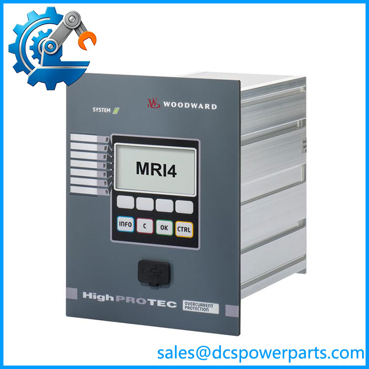
woodward–MRI4
Ground / Earth Fault Protection
Ground-current measurement is a major part of the architecture. Depending on the ordered hardware, the device can use conventional ground-current measurement or a sensitive ground-current input. That distinction matters in practice: sensitive inputs are intended for small ground-current measurement and should not simply be wired into a solidly grounded high-fault-current application without checking the applicable input limits and CT arrangement.
Negative-Sequence Protection
The relay supports negative-sequence/unbalanced-load protection. Woodward documents the I2/I1 relationship as a configurable protection criterion, allowing the relay to respond to current imbalance rather than looking only at absolute phase-current magnitude. This is useful where phase asymmetry can create thermal stress even though the individual phase currents have not reached the primary overcurrent threshold.
Thermal Replica
The includes a thermal replica function based on current loading. Parameters include base current, overload factor, warming time constant, and cooling time constant. The relay can expose calculated thermal capacity and remaining time to trip. This gives maintenance personnel more information than a simple instantaneous overcurrent element.
Breaker Control and Wear Monitoring
includes switchgear control functions and can monitor breaker operating counts and interrupted-current accumulation. The reference manual documents configurable breaker-wear thresholds and maintenance-related alarms. For substations with aging breakers, this information can be useful for maintenance planning without installing a separate monitoring device.
Programmable Logic
The relay is not limited to fixed protection equations. Its programmable logic can link protection signals, digital inputs, binary outputs, blocking conditions, acknowledgments, and control functions. That makes it considerably more flexible than a simple overcurrent relay, although the resulting logic should be documented as part of the protection settings package.
Disturbance and Event Recording
provides event, disturbance, fault, and trend recording functions. This is particularly useful during commissioning and post-trip investigation because the engineer can examine recorded electrical behavior rather than relying only on the final trip indication.
Flexible SCADA Integration
Communication is highly configuration dependent. The documented order code provides options including RS-485 with Modbus RTU, IEC 60870-5-103, or DNP3 RTU; Ethernet with Modbus TCP, DNP3, or IEC 60870-5-104; and higher-end IEC 61850 combinations. Do not assume an has Ethernet or IEC 61850 simply because another installation does.
Related Products
- MRA4 — Directional feeder protection relay for applications where directional current/ground-fault protection is required; functionally different from the non-directional .
- MRM4 — Motor protection relay from the same HighPROTEC generation, intended for motor-specific protection rather than general feeder protection.
- MRMV4 — Motor protection variant with voltage-related measurement/protection capabilities for applications requiring a broader motor protection package.
- MRDT4 — Transformer differential protection platform within the HighPROTEC family; intended for transformer differential applications rather than ordinary feeder overcurrent protection.
- MFR300 — Woodward multifunction relay and measuring transducer; useful where broader power measurement and multifunction protection are required, but it is not a direct hardware equivalent.
- — ordering family with the standard eight-digital-input/six-relay architecture; the remaining code determines current-input, mounting, communications, and PCB options.
- with sensitive ground input — configuration using the sensitive ground-current measurement hardware; important where the protection scheme requires low-level ground-fault measurement.
FAQ
Is the Woodward a PLC or DCS I/O module?
No. It is a numerical feeder protection relay. Its digital inputs and binary output relays may exchange signals with a PLC, DCS, or SCADA system, but the itself performs dedicated electrical protection functions.
What current-transformer rating does use?
The platform supports 1 A and 5 A nominal current inputs, depending on the ordered hardware. Phase-current measurement can extend to 40 × In, while ground-current capability depends on whether the standard or sensitive input arrangement is installed.
Can I hot-swap the ?
No — do not treat it as a hot-swappable PLC module. Removing a protection relay removes its protection functionality. The documentation specifically warns during commissioning/maintenance that removing the relay results in loss of protection and requires appropriate backup protection.
Does support Modbus TCP?
Some configurations do. The order-code documentation lists Ethernet variants supporting Modbus TCP, along with other protocols. Other units may have RS-485, fiber, PROFIBUS, or no communication interface. Check the complete order code and rear-panel hardware before specifying Modbus TCP.
Does support IEC 61850?
Selected communication configurations do. The ordering structure specifically identifies Ethernet-based variants with IEC 61850 communication, including combinations with Modbus TCP and DNP3. IEC 61850 should therefore be confirmed from the exact hardware order code rather than inferred from the model name alone.
Does the retain its protection settings after replacement?
Do not assume that a replacement unit contains the settings from the failed relay. The stores configuration and identifies its CAT No., revision, serial number, firmware version, and build information. Woodward also instructs users to cross-check the device nameplate part number and revision when obtaining configuration files.
Does support firmware version 3.1?
The generic model name does not establish a firmware revision. Current Woodward documentation identifies a device-model version and provides a separate firmware-version field. For procurement or engineering replacement, record the actual firmware/software information from the installed relay rather than assuming a version from the designation.
Can be used as backup protection for a transformer or generator?
Yes, within an appropriately engineered protection scheme. Woodward documents as suitable for feeder protection and as backup protection for generators, transformers, busbars, and electrical lines. The actual application still requires coordination studies, CT verification, trip logic review, and commissioning tests.
Procurement Note
The phrase “Woodward ” is not sufficient for a high-confidence like-for-like purchase. The actual ordering code determines at least the current-input arrangement, mounting style, communication hardware, and PCB configuration. Woodward’s reference manual shows the order-code structure explicitly.
For procurement, capture the complete CAT No., REV., S/N, firmware version, hardware variant, CT ratings, communication interface, and mounting arrangement from the existing relay. Woodward’s own configuration-file guidance states that the part number and revision on the nameplate should be cross-checked before installing a configuration file.
For a protection relay, this is not paperwork for paperwork’s sake. A unit with the wrong CT input, communication board, or protection configuration can physically fit the panel and still be the wrong device.
Before returning a replacement to service, verify CT polarity and ratio, ground-current wiring, digital-input thresholds, binary-output assignments, protection curves, trip delays, breaker-control logic, SCADA mapping, and the complete parameter set. Woodward recommends periodic protection testing, with the manual specifying a four-year protection-test interval that can be extended to six years when function testing is performed at least every three years.