Description
Product Overview
IS200TTURH1CCC is a turbine control terminal board, and its acronym describes its scope rather than its circuit: TTUR, the terminal board for the turbine. Where a servo terminal board lands actuator wiring and a trip termination board lands solenoids, this board lands the signals that describe the machine — the turbine’s speed pickups, its protection inputs, its temperature and shaft monitoring circuits, and the measurement channels that generator synchronization depends on. It is one of the few IS200 boards whose job is to be the cabinet’s connection to the turbine itself rather than to a specific subsystem.
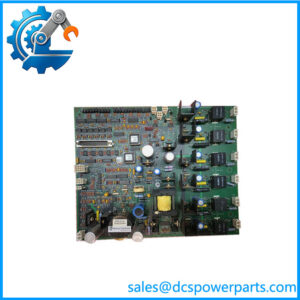
The board’s construction is documented closely enough to picture it. Two large terminal blocks carry the field wiring, with screw terminals numbered for reference so that a termination schedule can be followed rather than reconstructed. Six D-shell connectors — male and female both present — sit along the opposite edge and take the board’s signals into the rack and to the boards it works with, alongside plug connectors. Two transformers occupy the centre of the board, the largest magnetic components on it. Several surface-mount relays are fitted, so some actions are hard-wired at the board rather than routed through software, and variable resistors allow trim at the board. The board is essentially rectangular with a few small perforations.
The synchronization role is the one both the repair documentation and the parts documentation agree on: this board is used with the PTUR and VTUR boards to control the synchronization of the generator. That places it on the measurement side of the sync function — synchronization requires the control system to compare generator and bus voltage, frequency and phase angle, and to close the breaker at the moment those agree. The signals that comparison rests on arrive through field terminations, and it is this board that provides them. A drift in synchronization timing is therefore worth investigating at the terminations before it is blamed on the algorithm: a loose numbered terminal or a seated-but-not-latched D-shell produces exactly the kind of small, intermittent measurement error that shows up as a sync that will not quite settle.
Two jumper switches sit on the board and change its circuits for simplex or TMR voting. That is a configuration decision that must match the cabinet: a board jumpered for simplex in a TMR rack, or the reverse, will not misbehave visibly — it will simply vote wrongly, which is the failure mode that hides until the day redundancy is needed. Like every board in this generation, the jumper setting belongs in the commissioning record, not in someone’s memory.
The part number decomposes cleanly, and that decomposition is worth reading before ordering anything in this family. IS200 is the Mark VI board designation; TTUR is the functional acronym; H1 is the board group; C is the functional revision; and CC is the build field. The reason this matters is that the fields move independently: IS200TTURH1BCC is also in circulation — the same CC build on revision B — and IS200TTURH1BED applies that build field to a different revision again. A revision change therefore does not imply a build change, and a matching build field on a different revision is still a different board. On this example the printed assembly code S1DF00Z is a third identity layer again, as S1CX01H is on the TSVC boards and S1AT005-09 on the JPD boards — the catalog number, the build field and the assembly code are three separate statements, and the board is the only place all three appear together.
One caution about the sources. The variants of this board are sold under a range of descriptions, and at least one page labels IS200TTURH1C a “power distribution board” in its FAQ while its own title and photograph show a turbine control terminal board with terminal blocks, D-shells and transformers — a distribution board has no D-shell array and no voting jumpers. The description in this article follows the hardware: turbine control terminal board, field terminations and rack interconnect, two transformers, relays, trim resistors, and the two simplex/TMR jumpers.
Technical Specifications
| Parameter | Value |
|---|---|
| Model | IS200TTURH1CCC — IS200 + TTUR + H1 + revision C + build CC |
| Assembly code | S1DF00Z, printed on units of this build |
| Manufacturer | GE (General Electric), GE Boards & Turbine Control — made in USA |
| Product type | Turbine control terminal board (TTUR) |
| Series | Mark VI IS200; stated as compatible with Mark VI and Mark VIe cabinets |
| Field terminals | Two large terminal blocks, screw type, numbered for reference |
| Rack interconnect | Six D-shell connectors (male and female) plus plug connectors |
| Voting configuration | Two jumper switches, simplex or TMR |
| Board components | Two transformers at the board centre; surface-mount relays; variable resistors |
| Functional partners | PTUR and VTUR boards, used together for generator synchronization |
| Signal scope | Turbine speed pickups, protection inputs, temperature and shaft monitoring, synchronization measurement channels |
| Board shape | Essentially rectangular with small perforations |
| Sibling identities | IS200TTURH1C (base), IS200TTURH1BCC (same build on revision B), IS200TTURH1BED (different build) |
| Documentation status | No GE board-level datasheet in public circulation; description grounded in board hardware and repair documentation |
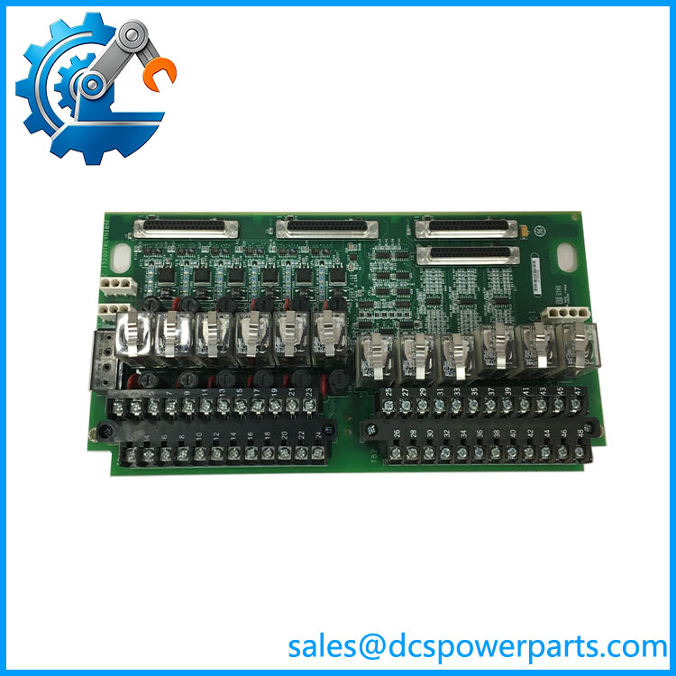
IS200TTURH1CCC
Key Features and Advantages
Numbered field terminations: two large screw terminal blocks with reference numbering, so a wiring schedule can be followed at the board instead of traced through a cabinet.
Direct rack interconnect: six D-shell connectors in both genders, plus plug connectors, which is how this board reaches the other PCBs it works with — the sync path in particular runs board-to-board rather than through loose wiring.
Voting selected at the board: two jumpers set simplex or TMR, so one board serves both cabinet architectures, and the setting is visible to anyone who looks rather than buried in a configuration file.
Hard-wired actions on board: surface-mount relays mean some functions do not depend on a processor being healthy, which is the point of a termination board in a protection path.
Trim where the signal is: variable resistors allow calibration at the board, which is the practical answer to a synchronization measurement that is consistently a little off.
Isolation in the signal path: two transformers at the centre are the board’s magnetic elements, and on a turbine terminal board that is where signal isolation is carried — an inference from the hardware, not a published specification.
Three-layer identity: catalog number, build field and printed assembly code all appear on the board, so a replacement can be matched exactly rather than approximately.
Independent fields: revision and build move separately across the family, which means H1BCC and H1CCC are both real and neither substitutes for the other.
Applications
Generator synchronization: the measurement side of the sync function, working with the PTUR and VTUR boards, where voltage, frequency and phase comparison depend on terminations made here.
Turbine speed measurement: the speed pickup channels that governor and overspeed functions rely on, terminated at the numbered blocks and taken into the rack through the D-shells.
Protection input termination: turbine protection signals entering the control system, including the hard-wired paths that the board’s relays support.
Temperature and shaft monitoring: RTD and shaft monitoring circuits whose field wiring arrives at this board rather than at a dedicated monitoring card.
TMR cabinets: installations where three channels are voted and the board’s jumper setting must match; a simplex-jumpered board in a TMR rack is a latent fault.
Retrofit and spares on Mark VI / Mark VIe turbine panels: where the installed board’s revision and build field both have to be matched, because the fields are independent.
Related Products
IS200TTURH1C — the base model without the build suffix; the reference identity for this design. IS200TTURH1BCC — the same CC build on revision B; proof that revision and build are separate fields and that neither substitutes for the other. IS200TTURH1BED — a different build field on revision B; same board family, different build. PTUR — partner board named in the synchronization documentation; the pair works together on generator synchronization. VTUR — the other named partner in the synchronization path, working with TTUR and PTUR. IS200TRPGH1BDD — primary trip termination board in the same cabinet, with a different function: solenoids and flame detectors rather than turbine measurement. IS200TSVCH1AED — servo I/O terminal board from the same rack generation, landing actuator wiring rather than turbine signals. IS200TBAIH1C — analog input terminal board in the same IS200 family, used where turbine measurements arrive through an analog input pack instead.
Installation and Maintenance
Before installation: match three things, not one — the revision, the build field, and the printed assembly code if the plant records it. Confirm the jumper setting for simplex or TMR against the cabinet’s voting architecture before the board goes in, since the wrong setting does not announce itself. Verify the synchronization partners are the PTUR and VTUR boards the cabinet expects, and check the replacement’s terminal numbering against the cabinet’s schedule.
Installation: land field wiring on the two numbered terminal blocks following the schedule, and record the mapping as it is removed rather than after. Seat all six D-shell connectors fully and confirm each is latched — a D-shell that is inserted but not locked is the classic cause of an intermittent sync or a speed channel that drops out under vibration. Set the two voting jumpers, leave the variable resistors at their factory positions until the loop is powered and a measurement can be compared, and only then trim. After wiring, verify continuity and insulation on the sync and speed channels before the machine is allowed to synchronize.
Maintenance: check the voting jumpers at every major outage, because they are the one setting on this board that changes behaviour without changing appearance. Inspect relays and variable resistors for ageing and drift, and the numbered terminal blocks for heat marks or loosened screws. When synchronization becomes marginal, test the field terminations and D-shell seating first, then the trim, and only then the algorithm — the failure hides in the wiring more often than in the logic. Hold spares at the exact revision and build, note the assembly code from the board, and treat a matching build on a different revision as a different part until the cabinet’s documentation says otherwise.
Warranty and Quality
Every IS200TTURH1CCC unit is supplied as the Mark VI turbine control terminal board, identified as IS200 + TTUR + H1 + revision C + build CC, with the printed assembly code S1DF00Z recorded where it appears on the board. Units are inspected for terminal-block condition and thread integrity, D-shell connector condition and latch function, jumper presence and setting, relay and variable-resistor condition, transformer mounting, board-edge and mounting wear, silkscreen and numbering legibility, the printed assembly code, and for evidence of prior repair or rework. The functional description is grounded in the board’s own hardware and in repair documentation rather than in marketing copy: two large numbered screw terminal blocks, six D-shell connectors in both genders plus plug connectors, two transformers at the centre, surface-mounted relays, variable resistors, and two jumper switches that select simplex or TMR voting, with the board used alongside the PTUR and VTUR boards for generator synchronization in Mark VI and Mark VIe cabinets. Claims that this part is a power distribution board are rejected — a distribution board has neither a D-shell array nor voting jumpers, and the board’s own photograph contradicts the description. Where the public record does not state a channel count or a voltage, this description does not invent one: the signal scope is stated in functional terms, and the electrical detail belongs to the cabinet documentation. A 12-month repair, replacement or refund commitment applies. Technical support covers what this part actually raises: confirming revision and build independently, setting the simplex/TMR jumpers to match the rack, diagnosing a marginal synchronization at the terminations before the algorithm, and matching the assembly code when the catalog number alone leaves the identity open.