Description
Product Overview
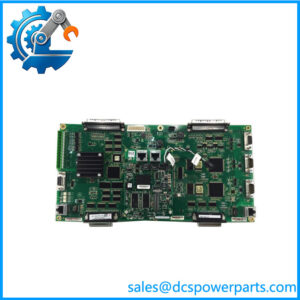
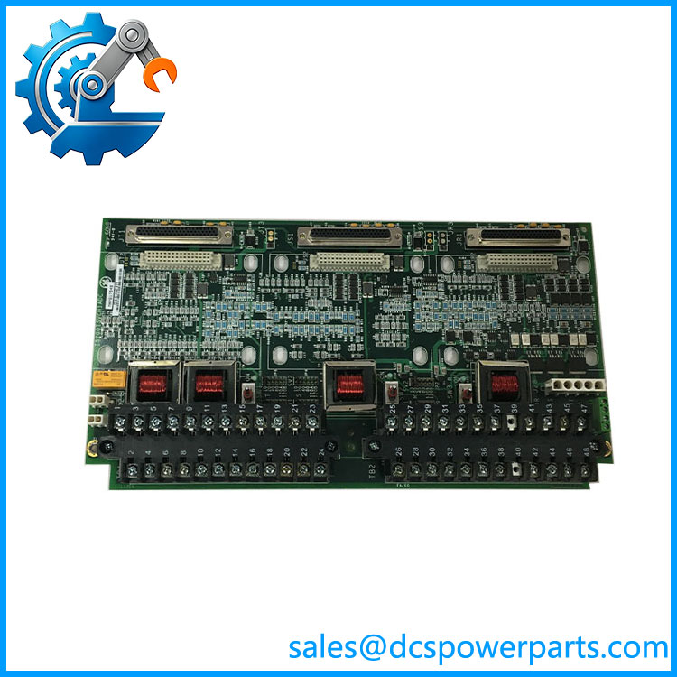
IS200TSVCH1ADC is a Mark VIe servo I/O terminal board in the TSVC family, and the only thing separating it from the AED board of the same base model is the two-letter build field at the end of the number. That is not a cosmetic difference. Each cable connector on a TSVC board carries a read-only identification device — serial number, board type, revision, J-connector location — which the I/O processor interrogates in operation, and a board type or revision that does not match what the processor expects raises a hardware incompatibility fault. Two boards can therefore be mechanically identical, pin-compatible, correctly wired, and still refuse to work together. Anyone ordering this part is buying an identity as much as a circuit board.
The circuit itself is the field-facing half of a servo loop. A servo valve’s torque motor is a coil that needs current in either direction to move the spool one way or the other, so the board’s two output channels are bidirectional current sources rather than voltage outputs — the pack regulates the current, the board delivers it to servo 1 and servo 2, and the coil current range is set by jumper: JP1 for servo 1 and JP4 for servo 2 in a simplex arrangement, JP1 through JP3 and JP4 through JP6 in a TMR arrangement where each servo output can carry three coils so that one failed coil does not end the loop. Everything beyond the coil current is configured in ToolboxST, which is where the loop’s scaling and calibration actually live.
Position feedback arrives on the same board. The TSVC family accepts LVDT inputs and reads the valve’s measured position rather than inferring it from the command, and one listing for this DC build quotes eight LVDT winding inputs with multiple excitation sources. The arithmetic behind that figure is worth doing, because it explains why a servo terminal board needs so many windings: an LVDT has one primary and two secondaries, so four windings per transformer; two regulators each carrying a dual-LVDT arrangement — the configuration in which the control system can drop a failed transformer and keep running on the good one — come to eight winding terminations. Whether the figure belongs to this exact build cannot be confirmed from the sources, but the topology it implies is the one the family’s diagnostics are built around.
The board also carries the safety-side and supply-side connections that make it usable in a turbine cabinet. Three 28 V DC supplies arrive through connector J28 and feed the servo valve control circuits; external trip wiring from the protection module lands on plug JD1 or JD2 so a protective trip can interrupt the servo command at the terminal board rather than only in software. The field wiring itself lands on two I/O terminal blocks of 24 terminals each, taking conductor up to 12 AWG, with a shield strip beside each block to bring cable screens to chassis reference at the board. Pulse-rate inputs are quoted for the family — magnetic pickup at 150 V p-p and active pickup at 5 to 27 V p-p on the AFD sibling’s specification — and their function on a servo board is not stated by the sources, so they are recorded as a capability rather than a purpose.
The pairing boundary is the part that decides which cabinet the board belongs in. TSVC is engineered for the PSVO I/O pack and the WSVO servo driver and is explicitly not compatible with the VSVO processor — the Mark VI VME servo card. That is the line between the Mark VIe servo architecture and the earlier Mark VI one, and it is why listings disagree about which series this board is: the family name gets applied loosely, while the pack it must satisfy does not. The environment figures are consistent with the platform: −30 to +65 °C operating, surface-mount construction, a board 33.02 cm high by 17.8 cm wide.
Technical Specifications
| Parameter | Value |
|---|---|
| Model | IS200TSVCH1ADC — base IS200TSVCH1A, build field DC |
| Manufacturer | GE (General Electric), Speedtronic turbine control — made in USA |
| Product type | Servo input/output terminal board (TSVC) |
| Platform | Mark VIe servo I/O; IS200 terminal board designation |
| Servo outputs | 2 channels, bidirectional current output; coil current selected by jumper |
| Coil current setting | Simplex: JP1 (servo 1), JP4 (servo 2); TMR: JP1–JP3 (servo 1), JP4–JP6 (servo 2) |
| Feedback | LVDT valve position inputs; eight winding terminations quoted for this build; dual-sensor arrangement deselects a failed transformer |
| Pulse-rate inputs | Quoted for the family: magnetic pickup 150 V p-p, active pickup 5–27 V p-p |
| Compatible packs | PSVO I/O pack and WSVO servo driver |
| Incompatible with | VSVO processor — the Mark VI VME servo card |
| Supply | Three 28 V DC supplies via connector J28 |
| External trip | Plug JD1 or JD2, wired from the protection module |
| Field terminals | 2 blocks × 24 terminals, wire to 12 AWG, shield strip adjacent to each block |
| Configuration | Jumpers for coil current; remaining parameters in ToolboxST |
| Diagnostics | Servo output current out of range; LVDT feedback out of range; dual-LVDT auto-deselect; composite alarm L#DIAG_PSVO; latched, cleared by RESET_DIA |
| Connector identification | Read-only ID device per cable connector — serial number, board type, revision, J-connector location; mismatch raises a hardware incompatibility fault |
| Redundancy support | Simplex, Dual, TMR |
| Environment and size | Operating −30 to +65 °C; surface-mount; 33.02 × 17.8 cm |
| Assembly code | S1CX01H observed on units of this build — board identity, not a catalog number |
| Sibling builds | IS200TSVCH1AED, H1AFD, H1AGE, H1AJE, and IS200TSVCH2A |
IS200TTURH1CCC
Key Features and Advantages
An identity the processor checks: the connector ID device stores board type and revision, so a wrong build is annunciated as a hardware incompatibility rather than left to produce plausible-looking but wrong valve behaviour.
Bidirectional current, not a voltage command: the output stage sources current in both directions for the torque motor, which is what a servo spool needs and what a voltage-output board cannot provide.
Coil current matched by jumper, per coil: JP1 and JP4 in simplex, JP1–JP3 and JP4–JP6 in TMR, so one build serves valves of different coil ratings and a TMR arrangement can set each of three coils independently.
Closed-loop position at the actuator: LVDT excitation and readback on the board that drives the coils, with the dual-sensor arrangement dropping a failed transformer instead of dropping the loop.
Trip available at the terminals: JD1 or JD2 accepts external trip wiring from the protection module, so a protective action interrupts the servo command at the field end.
Three independent 28 V DC feeds: J28 carries the supplies that the servo circuits need, and the redundancy of the supply is visible at the connector rather than assumed.
Wiring built for real cable: two 24-terminal blocks taking 12 AWG with adjacent shield strips, which is what a turbine hall’s screened cable actually requires.
Diagnostics that separate the two halves of the loop: servo current and LVDT feedback are monitored independently and resolve to L#DIAG_PSVO, so the fault points at the coil side or the feedback side rather than at “the servo”.
Applications
Steam turbine valve positioning: servo valves on steam admission and intercept valves, driven through two bidirectional current channels with LVDT feedback from the actuator.
Gas turbine fuel control: fuel regulating valves where the servo loop must respond fast and the trip path is required at the terminal board.
Duplex and TMR protection arrangements: configurations with three coils per servo output or two LVDTs per regulator, where the jumper scheme and the auto-deselect logic carry the redundancy.
LVDT-instrumented valves: installations where measured position comes from one or two transformers on the valve, including the dual-sensor arrangement that keeps running with one failed.
Replacement into an existing Mark VIe cabinet: where the installed board’s build field must be matched, not approximated, because the processor’s ID check will reject a different one.
Panels being converted from Mark VI servo hardware: where the VSVO architecture must be identified first, since TSVC is not compatible with it and the two are sold under the same family name.
Related Products
IS200TSVCH1AED — sibling build of the same base model with the ED field; mechanically interchangeable in appearance, not in identity. IS200TSVCH1AFD — sibling build with published pickup levels and size data, the reference for the family’s input conditioning. IS200TSVCH1AGE — sibling build described as interfacing two electro-hydraulic servo valves. IS200TSVCH1AJE — another build field in the same family, sold as a servo I/O PCB. IS200TSVCH2A — group 2 build, quoted with two coil outputs, two pulse-rate inputs and removable barrier terminal blocks. IS200TSVOH1B — the servo valve output terminal board of the adjacent design line; similar role, different pairing. IS220PSVOH1A — the PSVO I/O pack this board is designed to pair with. IS200VSVOH1B — the VSVO VME servo board, the Mark VI element this board is explicitly incompatible with. WSVO — the servo driver named as the other compatible partner in place of the PSVO pack.
Installation and Maintenance
Before installation: record the installed board’s model string and build field, and compare the replacement letter for letter — DC against ED is the whole difference and the whole risk. Confirm the pack is a PSVO or a WSVO and stop if the cabinet is built around VSVO. Check the three 28 V DC feeds are available at J28 and that the protection module’s trip wiring will land on JD1 or JD2.
Installation: land valve position sensors and servo valves on the two 24-terminal blocks, keeping conductor size within 12 AWG and bringing cable screens to the shield strip beside each block so the chassis reference is established at the board. Set the coil current jumpers against the valve’s torque motor rating — JP1 and JP4 for simplex, JP1–JP3 and JP4–JP6 for TMR — then complete the loop configuration in ToolboxST. Before energising, confirm the connector ID contacts are clean and undamaged, since a dirty ID contact produces the same fault as a wrong board and sends people looking for the wrong problem.
Maintenance: monitor servo output current and LVDT feedback separately; a current fault points at the coil or its cabling, a feedback fault at the transformer or its excitation. On a dual-LVDT regulator the failed transformer is dropped automatically, which keeps the machine running and hides a sensor that still needs replacement — log it rather than enjoying the redundancy. Clear latched diagnostics with RESET_DIA only after the cause is gone. Hold spares at the exact build field and record the assembly code with the serial number, because the processor compares exactly that data the next time the board is changed, and a substitute build will be rejected on the bench rather than in service.
Warranty and Quality
Every IS200TSVCH1ADC unit is supplied as the Mark VIe servo I/O terminal board, base model IS200TSVCH1A with the DC build field, and is described with both the capability and the boundary stated: two bidirectional servo current channels with LVDT position feedback, three 28 V DC supplies on J28, external trip on JD1 or JD2, two 24-terminal blocks accepting 12 AWG with shield strips, coil-current jumpers JP1/JP4 in simplex and JP1–JP3/JP4–JP6 in TMR, diagnostics on servo current and LVDT feedback with automatic deselection of a failed dual sensor and the L#DIAG_PSVO composite alarm cleared by RESET_DIA, connector ID devices carrying serial number, board type, revision and J-connector location, surface-mount construction at 33.02 × 17.8 cm, and an operating range of −30 to +65 °C — paired with the PSVO I/O pack or WSVO driver and explicitly not with the VSVO processor. Units are inspected for terminal-block condition and thread integrity, shield-strip continuity, jumper presence and position, connector and ID-contact condition, conformal surface condition, board-edge and mounting wear, silkscreen legibility, the printed assembly code, and for evidence of prior repair or rework. The DC field is treated as a required identity element rather than a catalogue variant, because the board’s own ID device is what enforces it. A 12-month repair, replacement or refund commitment applies. Technical support covers the questions this part raises in practice: which build field an installed cabinet will accept, how to tell a rejected board from a miswired one when the same fault appears either way, setting coil currents for the valve in hand, and reading L#DIAG_PSVO back to the coil side or the feedback side of the loop.
免费
今天 13:58