Description
Product Overview
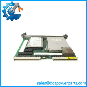
IS200TRLYH1BGF is the board in a GE turbine cabinet that turns logic into a contact. The functional name is precise about which version it is: TRLY, relay output with coil sensing. It holds twelve plug-in magnetic relays, and the sensing in its name refers to how it watches those relays — each coil’s current is compared with the command at the frame rate, and two consecutive disagreements latch an alarm. That is the property that separates this board from its TRLYH1C and TRLYH2C siblings, which watch contact voltage instead of coil current.
The twelve relays are not twelve of the same thing, and that distinction is the most useful thing to know about this board. Relays 1 through 6 are configured by jumpers for either dry Form-C contacts or to drive external solenoids, and a field solenoid supply is provided for them — a standard 125 V DC or 115/230 V AC source, or an optional 24 V DC source, with individually jumper-selectable fuses and on-board suppression. Relays 7 through 11 are unpowered, isolated Form-C contacts, pure switching with no supply behind them. Output 12 is also an isolated Form-C contact but is reserved for special applications such as ignition transformers, powered separately through connector JG1 — the document’s own figure annotates JG1 as available for gas turbine ignition transformers at 6 A at 115 V AC and 3 A at 230 V AC.
The supply arrangement is where installation mistakes concentrate. Solenoid power for outputs 1 to 6 arrives at JF1, and JF2 can daisy-chain that power to further TRLY boards; where neither plug is used, power can be wired directly to TB3, which accepts an alternate source of up to 20 A at 24 V DC, 125 V DC, 115 V AC or 230 V AC. The jumpers that enable per-circuit solenoid drive — JP1 through JP6 — are removed at the factory and shipped in a plastic bag, which means a replacement board arrives configured for dry contacts only. That is deliberate rather than accidental: energising a solenoid circuit requires a deliberate act, and the correct sequence is to conduct individual loop energisation checks and then install the jumpers where power is actually needed. For isolated contact applications the fuses are removed instead, so that suppression leakage cannot sit on the isolated bus.
The control side differs by platform but not by connector. In Mark VI the board is controlled by the VCCC, VCRC or VGEN board, and moulded-plug cables connect the terminal board to the VME rack where the I/O boards live; connector JA1 serves simplex systems, while JR1, JS1 and JT1 serve TMR. In Mark VIe the same board works with the PDOA I/O pack, which plugs into the DC-37 pin connectors on the terminal board, with the same connector allocation. In TMR the relay control signals are fanned in from the three I/O processors R, S and T through JR1, JS1 and JT1, voted, and the result drives the relay; the coil power comes from all three processors and is diode-shared, so one processor’s loss does not drop the coils.
The safety behaviour is a design feature rather than a diagnostic. The relay outputs have a failsafe that votes to de-energise the corresponding relay when a cable is unplugged or communication with the associated I/O processor is lost. A loose D-shell on this board therefore does not produce an arbitrarily held output — it produces a de-energised one, which is the failure direction a turbine cabinet wants.
The connectors carry identity as well as signals. Each terminal board connector has its own read-only ID device holding the board serial number, board type, revision number and the JR1/JS1/JT1 connector location; a mismatch when the I/O processor reads it creates a hardware incompatibility fault. Combined with the part number’s own fields — H1B for this design and GF as the build — the board tells the system exactly which board it is, and the system refuses it if the answer is wrong.
Technical Specifications
| Parameter | Value |
|---|---|
| Model | IS200TRLYH1BGF — base IS200TRLYH1B (TRLY, coil sensing), build field GF |
| Manufacturer | GE (General Electric) — GEH-6721 system documentation covers this part number explicitly |
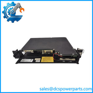
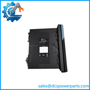
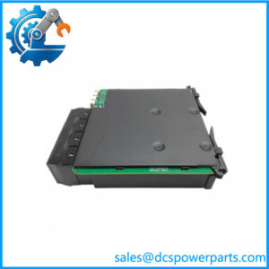
| Product type | Relay output terminal board, 12 plug-in magnetic relays |
| Control interface — Mark VI | VCCC, VCRC or VGEN board; moulded-plug cables to the VME rack |
| Control interface — Mark VIe | PDOA I/O pack on the DC-37 pin connectors |
| Redundancy connectors | JA1 simplex; JR1, JS1, JT1 for TMR — signals voted, coil power diode-shared from three processors |
| Relay channels | 12: relays 1–6 configurable for dry Form-C or solenoid drive; relays 7–11 dry, isolated; output 12 isolated, special circuit |
| Solenoid supply | Nominal 125 V DC or 115/230 V AC standard, optional 24 V DC; jumper-selectable fuses per circuit; on-board suppression |
| Special circuit supply | Output 12 via JG1; 6 A at 115 V AC, 3 A at 230 V AC for ignition transformer duty |
| Alternate power input | TB3, up to 20 A at 24 V DC, 125 V DC, 115 V AC or 230 V AC |
| Rated voltage | 125 V DC or 24 V DC nominal; 115/230 V AC |
| Maximum load current | 0.6 A at 125 V DC; 3.0 A at 24 V DC; 3.0 A at 115/230 V AC, 50/60 Hz |
| Response and inrush | 25 ms maximum on and off; maximum inrush 10 A |
| Contact ratings | 3.0 A relay rating; contact-to-contact 500 V AC for 1 minute; coil-to-contact 1500 V AC for 1 minute |
| Contact material and life | Silver cadmium oxide; 100,000 electrical operations, 10,000,000 mechanical operations |
| Suppression | 250 V metal oxide varistor between NO and power return on relays 1–6 |
| Field terminals | Two blocks × 24 terminals, up to 12 AWG, two screws per block, chassis shield strip at each block |
| Configuration | Jumpers JP1–JP12 (JP1–JP6 shipped removed, in a bag); fuses FU1–FU12; two fuses per powered circuit (e.g. FU1 + FU7 for output 1) |
| Diagnostics | Coil current versus command at frame rate; solenoid excitation voltage monitored downstream of fuses; relay contact voltage; composite L3DIAG_xxxx; ID-chip mismatch; latched and reset by RESET_DIA |
| Failsafe | Relay de-energises on unplugged cable or loss of communication with the I/O processor |
| Size and environment | 17.8 cm wide × 33.02 cm high (7 × 13 in); −30 to +65 °C |
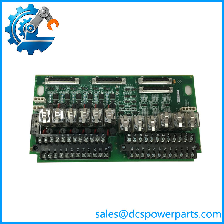
IS200TRLYH1BGF
Key Features and Advantages
Three relay classes on one board: six solenoid-capable channels, five dry isolated contacts and one special circuit rated for ignition transformer duty — so one board serves the cabinet’s mixed output requirements without interposing relays.
Coil sensing as a health signal: each relay’s coil current is checked against its command every frame, and two consecutive disagreements latch an alarm, catching a welded or open relay before the process depends on it.
Supply flexibility per circuit: 125 V DC, 115/230 V AC or optional 24 V DC, with individually selectable fuses, so the board adapts to the field device rather than forcing the device to adapt to the board.
Failsafe by vote: an unplugged cable or lost communication de-energises the relay instead of holding the last state, which is the correct direction for trip and alarm outputs.
TMR that reaches the coil: control signals from R, S and T are voted at the board, and coil power is diode-shared across the three processors, so the redundancy is not lost at the terminal board.
Suppression where it is needed: 250 V MOVs across the NO and power return of the solenoid circuits, absorbing the inductive kick of field solenoids at the board rather than in the wiring.
Wiring that can be documented and maintained: two numbered 24-terminal blocks taking 12 AWG, with chassis shield strips at each block, and barrier blocks that can be unplugged from the board for maintenance.
Deliberate energisation: JP1–JP6 arrive removed, so a board cannot power a solenoid until someone has performed the loop checks and installed the jumper — an engineering control built into the hardware.
Applications
Gas turbine ignition: output 12 and JG1 supply the ignition transformer circuit, with the 6 A at 115 V AC / 3 A at 230 V AC rating quoted for that duty.
Fuel and trip solenoid circuits: relays 1–6 driving field solenoids from a 125 V DC or AC supply, with suppression on board and fusing per circuit.
Alarm and annunciator outputs: the dry isolated contacts of relays 7–11 switching annunciator or interposing circuits with no supply of their own.
Plant interlock and permissive switching: Form-C contacts for start/stop commands, isolation of switching logic, and load circuit protection where a hard contact is required rather than a solid-state output.
Auxiliary and balance-of-plant loads on 115/230 V AC: the board’s AC rating allows direct switching of small AC circuits without an external interposing relay.
TMR cabinets: three-processor control with voted relay commands and diode-shared coil power, where the board’s JR1/JS1/JT1 fan-in is the mechanism that makes the redundancy real.
Retrofit and spares on Mark VI / Mark VIe panels: where the connector ID check and the build field both have to match, and where a board shipped with jumpers removed must be configured for the circuits that need power.
Related Products
IS200TRLYH1B — the base model, relay output with coil sensing; the design this build field belongs to. IS200TRLYH1C — sibling with contact sensing instead of coil sensing; relay coil monitoring removed, contact voltage monitoring added, snubbers fitted on the solenoid and special circuits. IS200TRLYH2C — the 24 V DC variant of the contact-sensing design, with 12 plug-in relays and six solenoid-capable circuits. IS200TRLYH1BED — a different build field on the same base; the field to compare when matching a replacement. VCCC — Mark VI controller that drives TRLY relay commands in one configuration. VCRC — the other Mark VI controller named for relay control. VGEN — generator-related Mark VI controller also documented as driving TRLY. PDOA — the Mark VIe I/O pack that plugs into the DC-37 connectors and provides the relay commands. IS200TREGH2BDC — trip termination board with twelve relays of its own, the alternative relay termination path in the protection architecture rather than the general output board.
Installation and Maintenance
Before installation: confirm the build field and check the platform — VCCC / VCRC / VGEN cabling in a Mark VI rack, or a PDOA pack on the DC-37 connectors in Mark VIe — and confirm which J connectors the redundancy level requires: JA1 for simplex, JR1, JS1 and JT1 for TMR. Inventory the jumpers, because JP1–JP6 arrive in a bag and a board installed straight from the box will not drive a solenoid.
Installation: land the twelve relay outputs on the two 24-terminal blocks following the wiring diagram, taking conductor up to 12 AWG and terminating cable screens at the chassis shield strip beside each block. Wire solenoid power for outputs 1–6 to JF1, daisy-chain through JF2 if other TRLY boards are to share it, or use TB3 with its 20 A alternate source; wire the output 12 special circuit supply to JG1. Perform individual loop energisation checks, then install JP1–JP6 only on the circuits that require solenoid power, and fit two fuses per powered circuit — FU1 with FU7 for output 1, and so on. For isolated contact applications, remove the fuses rather than leaving suppression leakage on the bus.
Maintenance: read the diagnostics rather than the symptom. A latched coil-current alarm means a relay disagreed with its command twice at the frame rate; a solenoid excitation alarm means the voltage downstream of the fuses fell below 12 V DC, which points at a fuse or the supply rather than the relay. Relay contact voltage is monitored as well, and the composite L3DIAG_xxxx narrows the field. Because the relays are plug-in magnetic types, a failed relay is a relay replacement rather than a board replacement, but the board must be de-energised and the circuit’s fuses accounted for first. Check the MOVs on circuits 1–6 for discoloration, and note the contact life figures — 100,000 electrical operations is a real wear limit on a circuit that switches frequently. Clear latched diagnostics with RESET_DIA only after the condition is healthy, and keep the jumper and fuse map in the panel record: the next technician needs to know which of the twelve channels is powered.
Warranty and Quality
Every IS200TRLYH1BGF unit is supplied as the Mark VI / Mark VIe relay output terminal board, base model IS200TRLYH1B with the GF build field, and is described from GE’s own system documentation for this part number (GEH-6721): twelve plug-in magnetic relays of which the first six are jumper-configurable for dry Form-C contacts or solenoid drive with a 125 V DC or 115/230 V AC supply (optional 24 V DC) and individually selectable fuses, relays 7–11 as unpowered isolated Form-C contacts, and output 12 as an isolated special circuit for ignition transformer duty through JG1 at 6 A / 115 V AC and 3 A / 230 V AC; control by VCCC, VCRC or VGEN in Mark VI or by the PDOA pack in Mark VIe; JA1 for simplex and JR1/JS1/JT1 for TMR with voted commands and diode-shared coil power; 0.6 A at 125 V DC and 3.0 A at 24 V DC or 115/230 V AC load ratings, 25 ms maximum response, 10 A maximum inrush, silver cadmium oxide contacts rated 100,000 electrical and 10,000,000 mechanical operations, 500 V AC contact-to-contact and 1500 V AC coil-to-contact isolation, 250 V MOV suppression on relays 1–6, two 24-terminal blocks accepting 12 AWG with chassis shield strips, 17.8 × 33.02 cm, and −30 to +65 °C. Units are inspected for terminal-block and screw condition, fuse holder condition, jumper presence against the shipped-in-bag convention, relay seating, MOV condition, D-shell and ID-contact condition, board-edge wear, silkscreen legibility, and for evidence of prior repair or rework. The coil-sensing identity is asserted as the defining difference from the H1C and H2C contact-sensing builds, and the GF field is treated as a required identity element. A 12-month repair, replacement or refund commitment applies. Technical support covers what this board actually raises: distinguishing coil sensing from contact sensing before a substitute is shipped, establishing which of the twelve channels are powered and which jumpers and fuses that requires, reading a latched coil-current or excitation-voltage alarm back to its cause, and confirming the connector ID will match the I/O processor that reads it.
免费
今天 14:42