Description
Product Overview
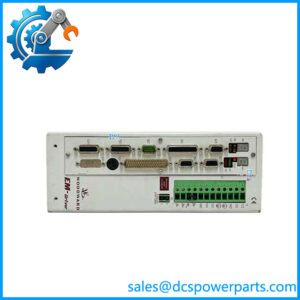
8237-1369 is not a part number that has to be guessed at, because Woodward documented its own product changes with more precision than most manufacturers document their products. In Product Change Notification 06912 (Revision B, June 2013) the ProTech-GII model table lists it line by line: “ProTech-GII — Panel Mount, HV/LV, voted relays, 8237-1369”, with its replacement 8237-1600 alongside. Three attributes are settled by that one line: the mounting style, the power supply arrangement, and the relay type — and each of them changes what the device does in a trip circuit.
The mounting style is physical. The bulkhead versions — 8237-1244 through 8237-1247 — mount through a wall or a bulkhead aperture, weigh approximately 12 kg, and carry an IP56 enclosure of their own. The panel versions, of which this is one, are built for installation in a panel or cabinet, weigh approximately 10 kg, and achieve IP56 only when installed in an IP56 enclosure. The difference in a plant is simple: a bulkhead unit can go on a wall near the machine, a panel unit goes in the control cabinet.
The power supply arrangement is the “HV/LV” in the description. Each of the three internal modules — A, B and C — accepts two independent power sources, and depending on the model those are either two high-voltage inputs (HV/HV) or one high-voltage and one low-voltage input (HV/LV). This unit is the mixed version: one input rated 90–264 V AC at 47–63 Hz or 100–150 V DC, nominally 115 V AC, 240 V AC or 125 V DC, and a second input rated 18–32 V DC, nominally 24 V DC. Woodward’s manual is explicit that each module functions normally with power on either or both inputs, that both are recommended to improve availability, and that the two supplies do not load-share internally — so the second input is redundancy, not capacity.
The relay type is the “voted relays” part, and it is the most consequential of the three attributes. In the independent-relay models each module carries three solid-state outputs rated 24 V DC at 1 A — two redundant trip signals and one alarm — and each set of trip relays typically drives one of three external trip solenoids in a 2-out-of-3 trip block. In the voted-relay models the three modules’ outputs feed a voting relay module inside the device, whose contacts are Form C dual SPDT capable of 8 A at 220 V AC or 8 A at 24 V DC, with a maximum switching voltage of 220 V AC or 150 V DC, 2000 VA or 192 W, and 1500 V AC isolation from contact to chassis. Put plainly: the independent version gives a designer three separate trip paths to wire outward; the voted version gives one voted trip contact set that can switch a real load directly. Ordering the wrong one is not a wiring adjustment.
The architecture behind all of it is triple modular redundancy with 2-out-of-3 voting — three modules, one speed input each (MPU or proximity probe, three in total), each with its own alarm relay and analog speed output, and voting logic that determines unsafe conditions without letting a single-point failure affect either reliability or availability. Failures in switches, transducers or modules are detected, annunciated, and repairable while the machine stays on line, which is the property that makes this device acceptable where a simple trip amplifier is not. The platform is certified by TÜV as an IEC 61508 SIL-3 device, complies with API 670, API 612 and API 611 when correctly installed, and may be applied as a stand-alone IEC 61508 device or inside an IEC 61511 plant safety system.
Its lifecycle status, however, is the reason this part number should be bought with open eyes. Woodward moved all original ProTech-GII models to “non-preferred” on 15 July 2013 and stated an intention to inactivate them within 12 to 18 months, having released the 2013 replacements as direct drop-in substitutes. In January 2018 a further generation was released — 8237-259x and 8237-260x — with the same functionality plus configurable speed-loss threshold, extended speed setting ranges to 80,000 rpm for turboexpander duty, a configurable acceleration filter, Chinese language support, and a reworked Modbus register map. 8237-1369 therefore sits two generations behind: its immediate successor is 8237-1600, whose successor is 8237-2600. Woodward states that it continues to support the non-preferred models under its support plan, and that units of Rev D or later can be converted in the field with the software conversion kit 8929-039 — which is the practical route if a plant wants the newer functions without replacing the hardware.
Technical Specifications
| Parameter | Value |
|---|---|
| Model | 8237-1369 — ProTech-GII, panel mount, HV/LV, voted relays |
| Manufacturer | Woodward, Inc., Fort Collins, Colorado, USA |
| Product type | Overspeed protection device, triple modular redundant, 2-out-of-3 voting |
| Configuration | Panel mount; one high-voltage and one low-voltage supply input per module; voted trip relays |
| Successor part numbers | 8237-1600 (PCN 06912, 2013); 8237-2600 (PCN 06946A, 2018) |
| Architecture | Three independent modules A, B, C; one speed input per module (MPU or proximity probe), 3 total; optional shared and voted inputs |
| Speed measurement | 0.5 to 32,000 rpm; sensing accuracy ±0.04 % of current speed over −20 to +60 °C |
| Response time | 8 to 26 ms, depending on model and configuration |
| Acceleration detection | Detectable over-acceleration 0 to 25,000 rpm/s; overspeed and acceleration trip setpoints configurable |
| High-voltage input | 90–264 V AC, 47–63 Hz, or 100–150 V DC; nominal 115 V AC / 240 V AC / 125 V DC; 30 W per module; inrush 10 A at 115 V AC, 20 A at 220 V AC |
| Low-voltage input | 18–32 V DC, nominal 24 V DC; 30 W per module; 1.5 A at 18 V DC, 1 A at 32 V DC; interrupt time 3 ms on one supply |
| Supply arrangement | Each module operates on either or both inputs; supplies do not load-share internally; each input requires its own breaker; PE ground required on high-voltage inputs |
| Voted trip relay | Form C dual SPDT, two channels actuated simultaneously; 8 A at 220 V AC / 8 A at 24 V DC; max switching 220 V AC or 150 V DC; 2000 VA / 192 W; isolation 1500 V AC |
| Module-level outputs | Per module: redundant trip outputs and one alarm relay, solid-state SPST normally open, 24 V DC at 1 A, isolation 500 V AC |
| Internal auxiliary supply | 24 V DC ±10 % at 500 mA for external relay coils, with internal over-current shutdown |
| Analog output | One speed output per module, 4–20 mA with configurable 4 mA and 20 mA scaling (0–32,000 rpm) |
| Communications | Modbus interface; front panel configuration; Programming and Configuration Tool (PCT, 9927-1810) |
| Environment | Operating −20 to +60 °C; storage −20 to +65 °C; RH to 95 % non-condensing; vibration 0.04 G²/Hz, 1.04 Grms, 10–500 Hz; shock 30 G, 11 ms; altitude to 3000 m |
| Enclosure | Panel mount version: IP56 when installed in an IP56 enclosure or cabinet; weight approximately 10 kg (22 lb) |
| Mounting | Vertical orientation; surrounding air must not exceed +60 °C at the final location |
| Measurement category | IEC Category I, withstands occasional transient overvoltages to 1260 V peak |
| Certification | TÜV SIL-3 per IEC 61508 Parts 1-7; API 670, API 612, API 611; certified for hazardous locations; EMC EN 61000-6-4 / EN 61000-6-2 |
| Cable limits | Speed signal 1500 ft / 457 m; relay signal 1000 ft / 305 m (low-capacitance 16 AWG) |
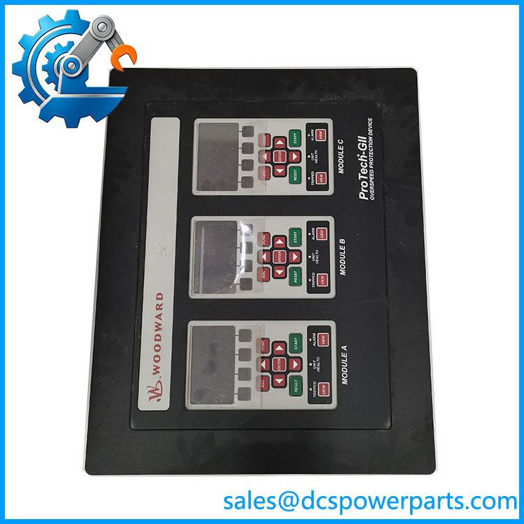
8237-1369
Key Features and Advantages
Three attributes in one part number: panel mount, HV/LV supply, voted relays. Each is a separate decision in a trip circuit, and Woodward’s own PCN table states all three explicitly — no inference required.
2-out-of-3 voting with on-line repairability: modules are independent, failures are detected and annunciated, and the machine keeps running on the healthy modules while the faulty one is replaced. Availability and safety are not traded against each other here.
Response in single-digit milliseconds: 8 to 26 ms from overspeed detection to trip, which is what an API 670 overspeed function on a large steam turbine requires.
Voted contacts that switch real loads: Form C dual SPDT rated 8 A at 220 V AC with 1500 V AC isolation, rather than a 24 V solid-state signal that needs an interposing relay.
Mixed supply architecture: one high-voltage input accepting 90–264 V AC or 100–150 V DC and one low-voltage 24 V DC input per module, so the device rides through the loss of either source, with no internal load sharing to confuse the design.
SIL-3 with a paper trail: TÜV certification per IEC 61508 Parts 1-7, compliance with API 670, 612 and 611, and use as a stand-alone IEC 61508 device or inside an IEC 61511 system.
Two upgrade routes rather than one: replace with 8237-1600 or 8237-2600, or, on units of Rev D or later, apply the field software conversion kit 8929-039 to gain the 2018 functions — including 80,000 rpm ranges for turboexpanders — on existing hardware.
Applications
Steam turbine overspeed protection: the primary application, with the voted relay set wired into the turbine trip circuit and three independent speed probes on the shaft.
Gas turbines and reciprocating engines: units where an overspeed event destroys the machine in seconds, and where the 8 to 26 ms response and 2-out-of-3 voting are the design basis.
Hydro turbines: low-speed machines within the 0.5 to 32,000 rpm range, where the configurable gear teeth and gear ratio settings adapt the device to the speed pick-up arrangement.
Compressors and process rotating equipment: API 670 duty on critical trains, where a stand-alone SIL-3 device is preferable to extending the plant DCS trip logic.
Plants migrating from ProTech 203: the newer generations include a configuration option that puts a module trip into the alarm latch logic the same way the original ProTech 203 did, which preserves existing annunciator behaviour.
Panel-mounted control cabinets in classified areas: IP56 achieved through the cabinet rather than the device, with the −20 to +60 °C operating range and hazardous-location certification supporting installation in a plant environment.
Where it does not belong: new applications, where Woodward itself directs buyers to the current model list, and installations needing the independent-relay wiring topology rather than a voted contact set.
Related Products
8237-1600 — the 2013 preferred replacement for this exact configuration: panel mount, HV/LV, voted relays. Direct drop-in substitute. 8237-2600 — the 2018 new model replacing 8237-1600; same configuration, extended ranges to 80,000 rpm and the reworked Modbus map. 8237-1370 — same panel mount and voted relays but HV/HV supply; the other half of this configuration pair. 8237-1367 / 8237-1368 — panel mount versions with independent relays, HV/LV and HV/HV respectively; the alternative trip topology. 8237-1246 — bulkhead mount, HV/LV, voted relays; the same electrical configuration in a wall-mounting enclosure. 8929-039 — Woodward’s field software conversion kit for Rev D or later units, the route to the 2018 functions without new hardware. 5437-1119 / 5437-1124 — spare module for the voted-relay models 8237-1596 and 8237-1600; the module-level spare for the voted configuration. 9927-1810 — the ProTech Service Tool / PCT, compatible with both older and newer ProTech-GII models. ProTech 203 — the predecessor device whose trip-to-alarm logic the ProTech-GII can emulate for existing annunciator schemes. 8237-2598 / 8237-2599 — the current panel-mount independent-relay models, if the wiring topology is to be changed rather than reproduced.
Installation and Maintenance
Before installation: confirm the configuration against the label, because three attributes that look interchangeable are not — panel or bulkhead, HV/LV or HV/HV, voted or independent relays. Verify the cabinet provides for a panel-mount unit, that the mounting is vertical, and that the surrounding air at the final location will not exceed +60 °C. Check that each power supply input has its own breaker, since Woodward requires separate disconnects to allow on-line module replacement, and that the high-voltage inputs have PE ground wires taken back to the source.
Installation: wire the high-voltage input within 90–264 V AC or 100–150 V DC and the low-voltage input within 18–32 V DC, remembering that neither input load-shares and that a configured input with no source will raise a continuous power supply fault alarm. Set the speed probe type — passive or active — on the front panel before commissioning, along with gear teeth (1 to 320) and gear ratio (0.10 to 10.0), because the overspeed setpoint is meaningless without them. Observe the 457 m limit on speed cabling and 305 m on relay cabling with low-capacitance 16 AWG, and treat the measurement inputs as Category I circuits with a 1260 V peak transient capability rather than as isolated signal inputs.
Maintenance: the design is built for on-line module replacement, so a detected and annunciated module failure is a scheduled task rather than an outage — but the replacement module must carry the same configuration, and Woodward notes that configuration files from the newer models cannot be loaded into the older ones, only the reverse. Run the Auto Sequence Test periodically to prove the trip path while the machine runs. Log the firmware and hardware revision: units of Rev D or later qualify for the field software conversion kit, units older than Rev D must return to Woodward, and that single letter decides which route a plant takes. Record the trip and alarm logs before any maintenance, since they are the evidence a safety review will ask for.
Warranty and Quality
Every 8237-1369 unit is supplied as the ProTech-GII panel-mount, HV/LV, voted-relay configuration, with its status stated as Woodward’s own non-preferred generation and its two-generation succession identified: 8237-1600 under PCN 06912 and 8237-2600 under PCN 06946A. Units are inspected for module and chassis condition, terminal and connector condition, front-panel display and keypad function, relay and voter module condition, label and revision legibility — the revision letter matters because Rev D or later is what qualifies for the field software conversion kit — and for evidence of repair or rework. Technical data is quoted from Woodward’s documentation: the ProTech-GII Installation and Operation Manual (26709, Rev J) for the platform specification — triple modular redundancy with 2-out-of-3 voting, 0.5 to 32,000 rpm with ±0.04 % sensing accuracy, 8 to 26 ms response, HV input 90–264 V AC or 100–150 V DC at 30 W per module, LV input 18–32 V DC at 30 W per module, voted trip relay Form C dual SPDT at 8 A / 220 V AC with 1500 V AC isolation, −20 to +60 °C operating, in an cabinet, approximately 10 kg, TÜV SIL-3 per IEC 61508 and API 670 / 612 / 611 — together with Product Change Notification 06912 Revision B and Product Change Notification 06946A for the part-number lineage, the preferred and new model tables, the conversion kit 8929-039, and Woodward’s statement that non-preferred models continue to be supported under its product support plan. Claims that this device is a “digital speed control” or a generic industrial control module are rejected: it is an overspeed protection device with voted trip relays, and its output stage is a safety function rather than a control signal. A 12-month repair, replacement or refund commitment applies. Technical support covers what this part actually requires: distinguishing voted from independent relays and HV/LV from HV/HV, identifying the correct successor part number, establishing whether a given unit is Rev D or later and therefore convertible rather than replaceable, and configuring probe type, gear data and setpoints so that the overspeed function responds to the machine rather than to the default.
免费
今天 11:31