Description
Product Overview
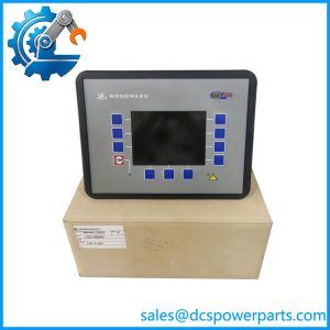
8237-1600 occupies the middle position in a three-generation family, and its significance lies in a phrase Woodward added to its description in 2013: “voted inputs”. Physically it is the same panel-mount, HV/LV, voted-relay ProTech-GII that the earlier 8237-1369 was — the same three-module assembly, the same Form C trip contacts, the same 10 kg panel unit achieving IP56 inside an IP56 cabinet. What changed was the wiring logic of the inputs, and that change is large enough that Woodward treated the 2013 release as a new model series rather than a revision.
The old arrangement gave each module its own speed input. Three probes, three modules, and each module voted on its own channel: a probe failure degraded the module that owned it, and the device detected and annunciated that failure but could not compensate for it. The voted-input generation shares every speed input with all three modules, so each module sees all three channels and each can be configured to use the median, the highest or the lowest of them for its alarm and trip logic. That is what the Speed Redundancy Manager block does: with all sensors healthy, the module selects median, HSS or LSS; with one sensor failed, it selects HSS or LSS; with two failed, it either issues a trip command or continues on the remaining healthy channel, as configured. It allows the use of three, two or one speed input sensors, and it includes a Speed Difference Detection alarm that doubles as a failed-sensor detector — active or passive probes included.
The Acceleration Redundancy Manager does the same for acceleration, with the same median, HSS and LSS selection and the same 3/2/1 sensor options, because an overspeed device that trips on acceleration needs its acceleration signal to survive a sensor loss just as its speed signal must. Between them, these two managers are the reason two-probe machinery can now use this device: Woodward notes that the new voting logic lets users configure voting to satisfy Shell’s 2-out-of-2 voting requirement where only two inputs are available or healthy.
The Boolean inputs were given the same treatment. The Start, Reset and Speed Failed Override commands of any module can be configured to accept the command from any or all of the other modules, ORed together — so a Reset issued at module A can reset module B if that is how the plant wants to operate. Woodward is specific about the boundary: these Boolean Input Manager functions can only be configured from the PCT service tool, not from the front panel, and the physical Start and Reset keys on a module’s faceplate still act only on that module.
The remaining changes in the 2013 release are the ones a plant notices in service rather than on paper. Failed Power Supply #1 and #2 alarms became individually configurable, so a single-supply installation can silence a nuisance alarm instead of living with it. The Speed Fail Alarm is overridden during turbine start, and the Speed Lost alarm and trip threshold moved from 100 Hz to 200 Hz, both of which remove nuisance trips on machines that roll slowly at start or run speed gears with fewer than 60 teeth. The Periodic Overspeed Test was renamed the Auto Sequence Test and gained both a “start now” command and a disable function, plus a configurable permissive that refuses to run a test while any module is in alarm or tripped. The trip latch became configurable as latching or non-latching; the speed probe type gained a “Not Used” setting so two probes can be wired into two modules without nuisance alarms on the third; the Peak Speed and Acceleration log gained date and time stamps; the configuration itself gained a change timestamp; a module trip can be folded into the alarm latch logic in the manner of the original ProTech 203; and the overspeed setpoint became readable as an analog register over Modbus.
Then there is the lifecycle, which a buyer needs stated plainly. These models were released on 17 May 2013 and became the preferred part numbers on 15 July 2013, with the earlier generation moved to non-preferred and “direct drop-in” status. In January 2018 Woodward released 8237-259x and 8237-260x, extending speed settings to 80,000 rpm for turboexpander duty, adding a configurable acceleration filter, Chinese language support and a reworked consecutive Modbus map — and moved this generation to non-preferred in turn. So 8237-1600 is now the middle of three, superseded by 8237-2600, and a unit of Rev D or later can be converted to the current generation in the field with Woodward’s software conversion kit 8929-039 rather than replaced. One compatibility rule is worth carrying into any upgrade: configuration files from older models load into newer ones, but never the reverse.
Technical Specifications
| Parameter | Value |
|---|---|
| Model | 8237-1600 — ProTech-GII, panel mount, HV/LV, voted relays, voted inputs |
| Manufacturer | Woodward, Inc., Fort Collins, Colorado, USA |
| Product type | Overspeed protection device, triple modular redundant, 2-out-of-3 voting |
| Speed inputs | 1 per module, 3 total; shared across all modules and voted in the voted-input generation; single input selectable as passive or active probe |
| Speed redundancy | Median, HSS or LSS selection; 3, 2 or 1 sensor operation; Speed Difference Detection alarm; supports 2-out-of-2 voting where two inputs are healthy |
| Acceleration redundancy | Median, HSS or LSS selection; 3, 2 or 1 sensor operation |
| Speed range | 0.5 to 32,000 rpm; sensing accuracy ±0.04 % of current speed over −20 to +60 °C |
| Response time | 8 to 26 ms, depending on model and configuration |
| Acceleration detection | 0 to 25,000 rpm/s detectable over-acceleration range; configurable trip setpoint |
| High-voltage input | 90–264 V AC, 47–63 Hz, or 100–150 V DC; nominal 115 V AC / 240 V AC / 125 V DC; 30 W per module |
| Low-voltage input | 18–32 V DC, nominal 24 V DC; 30 W per module; 1.5 A at 18 V DC, 1 A at 32 V DC; 3 ms interrupt time |
| Supply arrangement | Each module runs on either or both inputs; no internal load sharing; separate breaker per input; PE ground for HV inputs |
| Voted trip relay | Form C dual SPDT, two channels actuated simultaneously; 8 A at 220 V AC / 8 A at 24 V DC; max switching 220 V AC / 150 V DC; 2000 VA / 192 W; isolation 1500 V AC |
| Module outputs | Redundant trip outputs plus one alarm relay per module, solid-state SPST normally open, 24 V DC at 1 A, 500 V AC isolation |
| Internal auxiliary supply | 24 V DC ±10 % at 500 mA for external relay coils, with over-current shutdown and self-reset |
| Analog output | One speed output per module, 4–20 mA with configurable scaling (0 to 32,000 rpm default) |
| Communications | Modbus, including overspeed setpoint as an analog read register; front panel and PCT (9927-1810) configuration |
| Environment | Operating −20 to +60 °C; storage −20 to +65 °C; RH to 95 % non-condensing; vibration 1.04 Grms, 10–500 Hz; shock 30 G, 11 ms; altitude to 3000 m |
| Enclosure and weight | Panel mount, IP56 when installed in an IP56 enclosure; approximately 10 kg (22 lb); vertical mounting; ambient not above +60 °C |
| Certification | TÜV SIL-3 per IEC 61508 Parts 1-7; API 670, API 612, API 611; hazardous-location certified; EN 61000-6-4 / EN 61000-6-2 |
| Upgrade route | Field software conversion kit 8929-039 for Rev D or later units; spare module 5437-1119 / 5437-1124 |
| Documentation | Installation and Operation Manual 26709 (Rev J); Product Change Notifications 06912 and 06946A |
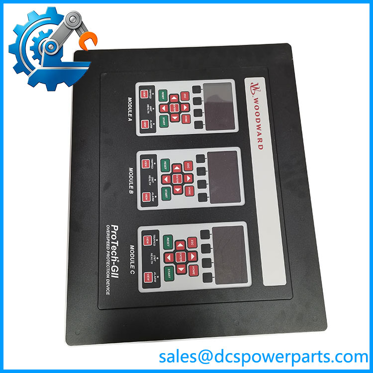
8237-1600
Key Features and Advantages
Inputs that survive a sensor: three speed channels shared across three modules, with median, HSS and LSS selection and a Speed Difference Detection alarm that identifies the failed probe rather than merely losing its channel.
Two-probe machinery accommodated: the voting logic can be configured for Shell’s 2-out-of-2 requirement where only two inputs are available — an option the earlier generation did not offer at all.
Acceleration gets the same treatment: an Acceleration Redundancy Manager with the same selection modes, because a trip on acceleration is as dependent on a healthy channel as a trip on speed.
Commands that cross modules when you want them to: Start, Reset and Speed Failed Override configurable to accept any module’s command, ORed — configured through the PCT only, with the faceplate keys deliberately left acting on their own module.
Nuisance trips engineered out rather than tolerated: configurable individual power supply alarms, Speed Fail Alarm override during start, and the Speed Lost threshold raised from 100 Hz to 200 Hz for slow-rolling machines and low-tooth-count gears.
A test routine that can be trusted as evidence: the Auto Sequence Test with an explicit start command, a disable function, a permissive that refuses to start while any module is alarmed or tripped, and a result reported for the whole sequence rather than the local module.
A trip latch that suits the plant’s philosophy: latching or non-latching, and a “Trip is Alarm” option that reproduces the ProTech 203 annunciator behaviour without rewiring the logic.
A clearly bounded upgrade path: this generation is superseded, but Rev D or later units convert in the field with 8929-039, and configuration files carry forward from old to new — not the reverse.
Applications
Steam turbines with three speed probes: full 2-out-of-3 voting on three channels, with the redundancy managers selecting a reliable value when a probe or its cabling fails.
Machines with only two speed pick-ups: the two-input configuration the 2013 logic introduced, meeting a 2-out-of-2 voting requirement where a third probe cannot be fitted.
Hydro units and slow-rolling machines: the 200 Hz Speed Lost threshold and the Speed Fail override during start remove the alarms that low speeds and low gear-tooth counts used to generate.
Gas turbines and reciprocating engines: API 670 overspeed duty with an 8 to 26 ms trip path and voted Form C contacts switching the trip circuit directly.
Compressors and turboexpanders within the 32,000 rpm limit: critical rotating trains where a stand-alone SIL-3 device is preferred to extending the plant DCS.
Plants with mixed module populations: where an older unit is being replaced by this generation as a drop-in substitute, or where a Rev D or later unit is being converted to the current generation with 8929-039.
Where it does not belong: applications above 32,000 rpm — that needs the 2018 generation, which extended the setting range to 80,000 rpm — and installations requiring an independent-relay trip topology rather than a voted contact set.
Related Products
8237-2600 — the current successor, released January 2018; same configuration, extended speed settings to 80,000 rpm, reworked Modbus map. 8237-1369 — the predecessor this model replaced in 2013; same panel-mount HV/LV voted-relay configuration without the voted-input logic. 8237-1596 — bulkhead-mount equivalent with the same HV/LV and voted-relay configuration. 8237-1598 / 8237-1599 — panel-mount independent-relay models in HV/LV and HV/HV, the alternative trip topology. 5437-1119 / 5437-1124 — spare module for the voted-relay models 8237-1596 and 8237-1600; non-preferred and preferred part numbers respectively. 8929-039 — field software conversion kit, applicable to Rev D or later units of this generation. 9927-1810 — the ProTech Service Tool / PCT, required for the Boolean Input Manager configuration. 26709 — the Installation and Operation Manual (Rev J) documenting this model family and its specification tables. 35086 — the manual for the 2018 generation, the reference for a converted or replaced unit. ProTech 203 — the predecessor device whose trip-to-alarm logic can be reproduced in this model’s configuration.
Installation and Maintenance
Before installation: confirm the label reads 8237-1600, panel mount, HV/LV, voted relays — this generation and its predecessor share a form factor, so the part number rather than the appearance is the evidence. Verify the cabinet gives IP56, the mounting is vertical, and the ambient at the final location stays at or below +60 °C. Provide separate breakers for each supply input, with the high-voltage input within 90–264 V AC or 100–150 V DC and the low-voltage input within 18–32 V DC, and confirm the low-voltage input is not treated as a capacity supplement — the two do not load-share.
Installation and configuration: set the probe type — passive, active, or Not Used where only two probes are fitted — along with gear teeth (1 to 320) and gear ratio (0.10 to 10.0), since the overspeed setpoint depends on them. Configure the Speed and Acceleration Redundancy Managers and, if the plant wants cross-module commands, the Boolean Input Manager — all through the PCT, because those functions are not reachable from the front panel. Choose the trip latch behaviour with the trip circuit in mind, decide whether a trip should also appear as an alarm, and keep speed cabling within 457 m and relay cabling within 305 m of low-capacitance 16 AWG.
Maintenance: run the Auto Sequence Test on the schedule the plant’s proof-test interval requires, remembering that a test will not start while any module is alarmed or tripped — the permissive is a feature, not a fault. Treat the configuration as the asset: download it before any module replacement, since a spare module 5437-1119 or 5437-1124 arrives unconfigured, and note the direction rule if the population is being upgraded — old files load into new models, new files never load into old ones. Record the revision letter on each module: Rev D or later is what qualifies a unit for conversion with 8929-039, and that single letter decides whether the plant upgrades the software or replaces the hardware.
Warranty and Quality
Every 8237-1600 unit is supplied as the ProTech-GII panel-mount, HV/LV, voted-relay model of the 2013 generation with voted inputs, and is described with its position in the family made explicit: it replaced 8237-1369, and it was itself superseded by 8237-2600 in 2018. Units are inspected for module and chassis condition, terminal and connector condition, front-panel display and keypad function, voting relay module condition, label and revision legibility — the revision letter determining eligibility for the field conversion kit — and for evidence of repair or rework. Technical data is quoted from Woodward’s documentation: the Installation and Operation Manual 26709 (Rev J) for the platform and its specification tables — three speed inputs shared and voted across modules A/B/C, median / HSS / LSS selection with 3-, 2- or 1-sensor operation and Speed Difference Detection, an equivalent Acceleration Redundancy Manager, 0.5 to 32,000 rpm at ±0.04 % accuracy, 8 to 26 ms response, HV input 90–264 V AC or 100–150 V DC at 30 W per module, LV input 18–32 V DC at 30 W per module, voted trip relay Form C dual SPDT at 8 A / 220 V AC with 1500 V AC isolation, −20 to +60 °C, IP56 in an cabinet, approximately 10 kg, TÜV SIL-3 to IEC 61508 with API 670 / 612 / 611 compliance — together with Product Change Notification 06912 Revision B for the 2013 model table and the twenty-three functional changes that define this generation, and Product Change Notification 06946A for the 2018 succession to 8237-259x / 8237-260x and the applicability of conversion kit 8929-039. Claims describing this device as a digital speed controller are rejected: it is an overspeed protection device whose output is a safety trip. A 12-month repair, replacement or refund commitment applies. Technical support covers what this part actually requires: distinguishing it from its predecessor and successor by part number rather than by appearance, configuring the redundancy managers and Boolean Input Manager through the PCT rather than the front panel, establishing whether a unit is Rev D or later and therefore convertible, and keeping the configuration files travelling in the one direction Woodward permits.