Description
Product Overview
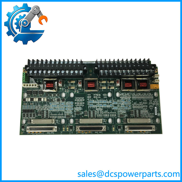
IS200TSVCH1AED is the field-facing half of a servo loop in GE’s Mark VIe turbine control. The architecture splits the job in two: an I/O pack does the computation and the current regulation, and a terminal board lands the field wiring, conditions the signals and provides the physical and electrical interface to the servo valve hardware. This part is the second of those two, and its functional acronym says so — TSVC, the servo input/output terminal board, as distinct from the pack that drives it.
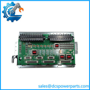
The composition is the useful part of the description, because it tells an engineer what a servo loop in a Mark VIe panel actually looks like at the terminals. The board carries two servo coil outputs — servo 1 and servo 2 — which drive the electro-hydraulic servo valves that position the steam or fuel valves on a turbine. It carries LVDT inputs for valve position feedback, so the loop is closed at the valve rather than inferred from a command; the board excites the Linear Variable Differential Transformer and reads its output, and the control system uses that as the measured position. It carries two pulse-rate inputs as well, and quotes pickup levels for both passive and active types — 150 V peak-to-peak for a magnetic pickup and 5 to 27 V peak-to-peak for an active one — which is the input conditioning a terminal board of this class typically provides. What role those pulse-rate channels serve on a servo board is not stated by the sources, so it is reported here as a capability rather than as a function.
The board also carries the safety-side connections. Three 28 V DC power supplies arrive through connector J28 and feed the servo valve control circuits, and external trip wiring from the protection module lands on plug JD1 or JD2 so that a protective trip can interrupt the servo command at the board rather than only in software. Both of those are the kind of detail that decides whether a spare will actually restore a unit: a board with no trip input is not a substitute for one with it.
The pairing rule is the sharpest constraint in the whole description. This terminal board is engineered for the PSVO I/O pack and the WSVO servo driver, and it is explicitly not compatible with the VSVO processor — the Mark VI VME servo card. That boundary separates the Mark VIe servo architecture from the earlier Mark VI one, and it explains why the same board is described by some sellers as Mark VI and by others as Mark VIe: the family name is used loosely, while the hardware pairing is exact. A buyer who treats those two servo architectures as interchangeable will end up with a board that fits the rack and fails the ID check.
Redundancy is handled at the jumper level as well as in software. The board supports simplex, dual and TMR configurations. In simplex, each servo valve needs its coil current set individually — jumper JP1 for servo 1 and JP4 for servo 2. In TMR, each servo output can accommodate three coils so that a single failure does not end the loop — JP1 through JP3 for servo 1 and JP4 through JP6 for servo 2, one jumper per coil. Everything beyond the coil currents is configured in ToolboxST.
Then there is the property that makes this part number’s suffix matter more than its appearance. Every cable connector on the terminal board has an associated ID device — a read-only chip holding the serial number, board type, revision number and J-connector location — and the I/O processor interrogates it at operation. If the board type or revision does not match what the processor expects, a hardware incompatibility fault is raised. In plain terms: an AED board and an ADC board from the same family are not interchangeable just because they seat, and the fault they raise will point at hardware compatibility rather than at the wiring someone just disturbed.
Technical Specifications
| Parameter | Value |
|---|---|
| Model | IS200TSVCH1AED — base IS200TSVCH1A, build/variant suffix ED |
| Manufacturer | GE (General Electric), Speedtronic turbine control — made in USA |
| Product type | Servo input/output terminal board (TSVC) |
| Platform | Mark VIe servo I/O; IS200 terminal board designation |
| Servo outputs | 2 servo coil outputs — servo 1 and servo 2 |
| Feedback | LVDT valve position inputs, closed-loop feedback to the control system |
| Pulse-rate inputs | 2 channels (quoted for the H2A sibling); magnetic pickup 150 V p-p, active pickup 5–27 V p-p |
| Compatible packs | PSVO (Primary Servo Valve Output) I/O pack and WSVO servo driver |
| Incompatible with | VSVO processor — the Mark VI VME servo card |
| Supply | Three 28 V DC supplies via connector J28 |
| External trip | Plug JD1 or JD2, wired from the protection module |
| Field terminals | 2 I/O terminal blocks, 24 terminals each, two fixing screws per block, wire up to 12 AWG; shield terminal strip adjacent for chassis ground |
| Redundancy support | Simplex, Dual, TMR |
| Coil current setting | Simplex: JP1 (servo 1), JP4 (servo 2); TMR: JP1–JP3 (servo 1), JP4–JP6 (servo 2) |
| Configuration | Jumpers for coil current; remainder via ToolboxST |
| Diagnostics | Servo current out-of-range, LVDT feedback out of range, dual-LVDT auto-deselect of a failed sensor, composite alarm L#DIAG_PSVO, latched with RESET_DIA |
| Connector identification | Read-only ID chip per cable connector: serial number, board type, revision, J-connector location; mismatch raises a hardware incompatibility fault |
| Environment | Operating −30 to +65 °C |
| Construction | Surface-mount technology; board size 33.02 × 17.8 cm |
| Variant siblings | IS200TSVCH1ADC, H1AFD, H1AGE, H1AJE, and IS200TSVCH2A — different build fields |
IS200TSVCH1AED
Key Features and Advantages
Two servo channels on one board: servo 1 and servo 2 coil outputs with independent current selection, which is what a duplex or TMR valve arrangement needs at the field end.
Closed-loop position at the valve: LVDT excitation and feedback on the same board that drives the coils, so the measured position comes from the actuator rather than from a model of it.
Coil current matched to the valve, not to a default: JP1 and JP4 in simplex, JP1–JP3 and JP4–JP6 in TMR — the jumper scheme lets one board build serve valves with different coil currents without a different part number.
Redundancy that reaches the terminals: the TMR configuration accepts three coils per servo output, so the redundancy claimed by the pack is not defeated by the field wiring.
Trip path at the board: external trip wiring on JD1 or JD2 lets the protection module interrupt the servo command at the terminal board, and three 28 V DC feeds on J28 keep the servo circuits supplied independently.
Field wiring that survives an outage: two 24-terminal blocks accepting up to 12 AWG, with a shield strip beside each for chassis ground — sized for real cable rather than for a quick-connect harness.
Diagnostics that identify the failing half: servo current and LVDT feedback are checked separately, a dual-sensor arrangement drops a failed LVDT automatically, and the composite alarm resolves to L#DIAG_PSVO with details in ToolboxST.
Revision-aware architecture: the connector ID chip means a wrong build is detected and annunciated instead of half-working — the mechanism that makes the ED suffix a specification rather than a footnote.
Applications
Steam turbine valve actuation: the servo valves positioning steam admission and intercept valves, with LVDT feedback closing the loop at the actuator.
Gas turbine fuel control: fuel regulating and control valves driven through two servo coil outputs, with the trip path available at JD1 or JD2.
Turbine governor loops: servo positioning where the loop must respond quickly to speed error, and where the pack’s current regulation needs a terminal board with genuine shielding.
TMR-protected units: triple-redundant servo configurations using three coils per output, where the terminal board’s jumper selection per coil matters as much as the pack’s voting.
LVDT-based position feedback installations: valves instrumented with one or two LVDTs, including the dual-sensor arrangement that deselects a failed transformer without dropping the loop.
Retrofit and spares on Mark VIe panels: where a TSVC board has failed and the replacement must satisfy the connector ID check, not merely seat in the rack.
Not applicable to Mark VI VSVO servo architectures — the incompatibility is stated explicitly — and not a substitute for the TSVO terminal board used with a different servo arrangement.
Related Products
IS200TSVCH1ADC — the same base board with the DC build field; a variant that will raise an ID mismatch if fitted where an ED is expected. IS200TSVCH1AFD — sibling build with published pickup and size data; another variant of the same terminal-board design. IS200TSVCH1AGE — sibling described as interfacing two electro-hydraulic servo valves; the GE build field. IS200TSVCH1AJE — another suffix in the same family, sold as a servo I/O PCB. IS200TSVCH2A — the H2 group build, quoted with two coil outputs and two pulse-rate inputs and removable barrier terminal blocks. IS220PSVOH1A — the PSVO I/O pack this terminal board is designed to pair with; the pack side of the servo loop. IS200VSVOH1B — the VSVO VME servo board, the Mark VI element the board is explicitly not compatible with. IS200TSVOH1B — the servo valve output terminal board of the adjacent design line; visually similar, functionally a different pairing. WSVO — the servo driver named as the other compatible partner, the alternative to the PSVO pack.
Installation and Maintenance
Before installation: confirm the build field on the board and on the paperwork — AE, AF, AG, AJ variants sit in the same family and the connector ID check will reject a mismatch, so matching the suffix is part of the work, not a formality. Verify the pack side is a PSVO or a WSVO, and stop if the panel is built around VSVO. Confirm three 28 V DC feeds are available for J28 and that the protection module’s trip wiring will land on JD1 or JD2.
Installation: wire valve position sensors and servo valves to the two I/O terminal blocks, each with 24 terminals, keeping conductor size within 12 AWG and landing shields on the strip beside each block so the chassis reference is established at the board rather than somewhere in the cabinet. Set the coil current jumpers — JP1 and JP4 for a simplex arrangement, JP1–JP3 and JP4–JP6 for TMR — against the valve’s coil rating, then finish the configuration in ToolboxST. Perform continuity and insulation resistance checks, and test the servo outputs and the external trip path before returning the loop to service.
Maintenance: watch the two diagnostics that matter — servo current out of range and LVDT feedback out of range — and use ToolboxST to read the detail behind L#DIAG_PSVO rather than resetting it. On a dual-LVDT regulator, a failing transformer is dropped from the feedback calculation automatically, which keeps the unit running but also hides a sensor that needs replacing; record it. Latch and clear diagnostics deliberately with RESET_DIA only after the underlying condition is healthy. Hold spares at the exact build suffix, and keep the board’s ID data in the asset record alongside its serial and revision, because that data is what the processor will compare next time the board is changed.
Warranty and Quality
Every IS200TSVCH1AED unit is supplied as the Mark VIe servo I/O terminal board, base model IS200TSVCH1A with the ED build field, and is described with its pairing stated explicitly: PSVO I/O pack and WSVO servo driver, not the VSVO processor. Units are inspected for terminal-block condition and thread integrity, shield-strip continuity, jumper presence and setting, connector condition including the ID device contacts, board-edge and mounting wear, silkscreen legibility, and for evidence of prior repair, rework or component replacement. Technical data is drawn from the documentation circulated for the TSVC family: two servo coil outputs with LVDT valve position feedback, two pulse-rate inputs quoted for the H2A build with magnetic pickup at 150 V p-p and active pickup at 5 to 27 V p-p, three 28 V DC supplies via J28, external trip on JD1 or JD2, two 24-terminal blocks accepting 12 AWG with adjacent shield strips, simplex / dual / TMR support, coil-current jumpers JP1 and JP4 in simplex and JP1–JP3 / JP4–JP6 in TMR, diagnostics for servo current and LVDT feedback with automatic deselection of a failed dual sensor and the composite alarm L#DIAG_PSVO resettable by RESET_DIA, connector ID devices carrying serial number, board type, revision and J-connector location, surface-mount construction at 33.02 × 17.8 cm, and an operating range of −30 to +65 °C. The board’s Mark VIe placement is asserted on the basis of its documented PSVO / WSVO pairing rather than on the loose “Mark VI” labelling common in listings, and the ED suffix is treated as a required identity field, not a cosmetic difference. A 12-month repair, replacement or refund commitment applies. Technical support covers what this part actually requires: identifying which build suffix an installed panel will accept, distinguishing TSVC from TSVO and from the VSVO architecture, setting coil current jumpers for the valve in hand, and reading L#DIAG_PSVO back to the failing half of the loop.