Description
Product Overview
500MBA02 is the module that makes a REC 580 bay control terminal able to talk to its process. The official wording in ABB’s REC 580 manual is short and complete: “The process bus controller module has its own processor and controls the exchange of data via MVB.” There is no ambiguity to work around, and no need to infer a role from the surrounding part numbers — which is worth saying explicitly, because this module has been described elsewhere as a bus coupling module, a terminology the manual never uses. Its function is controlling data exchange over the process bus, and the “controller” in its official name is literal.
The bus it controls is the process-level bus of the REC 580, and the design intent is the reason the module exists at all. ABB describes the process bus as an important innovation because it “dramatically reduces the volume of control wiring running through the station” and allows intelligent sensors and actuators to be used at the switchgear instead of hard-wired marshalling. A REC 580 has three communication levels, and they are physically separate: the station bus LON at the rear, for data exchange with the station control level and with other bay control units and protection devices; a service port on the front, optical RS 232 for a standard PC; and the process bus MVB at the rear, which carries communication with the extension rack and with sensors and actuators through the PISA optical interface.
The module is a processor in its own right, not a passive interface. That matters structurally: the REC 580’s internal architecture is a VME bus per IEC 821, and functions run in parallel across more than one CPU. The application programs live in the processor module 500CPU03, which also acts as the VME bus controller and carries two Industry Pack sockets — C for 500LBI02, the LON station bus interface, and D for 500PBI01, the internal process bus interface. 500MBA02 sits alongside that pair as the rack-level MVB controller. The practical consequence is a pairing rule that installations get wrong: an MBA02 on its own does not give a CPU access to the process bus. The manual states that when an extension rack is connected, the 500CPU03 in the basic rack “shall be provided with a 500PBI01 in the Industry Pack slot D” alongside the MBA02 in the rack. Two modules, two different places, one bus.
Where it may be fitted is equally specific. The 21-slot basic rack accepts 500MBA02 at one fixed position — the manual’s slot configuration table shows a single permissible position for it, in contrast to the binary input, binary output and star coupler modules, which are shown as placeable across a range of middle slots. And the extension rack, which uses the same physical layout, is defined as not carrying “a processor, adapter, and process controller modules”. So the bus controller belongs to the basic rack only; an extension rack is reached through it, not equipped with one. That is consistent with the topology the manual describes: extension racks connect to the basic rack over the MVB process bus, with a star coupler 500SCM01 converting the electrical bus signals into optical ones, two fibre cores per bay unit, 62.5/125 µm, a maximum permissible attenuation of 5 dB, and approximately 1200 m of length.
All of this places 500MBA02 in a platform that the part number itself does not reveal. The 500-series names — PSM, CPU, MBA, SCM, BIM, BOM, AIM, MTM, ITM — are often sold in the secondary market as “Procontrol P13/P14 rack I/O”, a lineage that fits the numbering style but not the documentation. The REC 580 manual defines each of these modules one by one, in its own words, inside a numerical bay control terminal for complex high-voltage substations, part of the ABB PANORAMA station automation system: auxiliary supply units of 60 W and 100 W feeding from 36 to 312 V DC without range switching, a processor module with Industry Pack sockets, a process bus controller, a star coupler, input transformer and isolating transducer modules, and analog, binary input and binary output units. The correct lineage for this module is that rack, not a P13/P14 I/O cage.
Technical Specifications
| Parameter | Value |
|---|---|
| Model | 500MBA02; module order code 1MRB150003R0003 (as sent: 1MRB150003R000B) |
| Manufacturer | ABB — ABB PANORAMA station automation system |
| Product type | Process bus controller module, REC 580 bay control terminal |
| Official function | Controls the exchange of data via MVB; equipped with its own processor |
| Bus | MVB process bus, optical interface at the rear of the terminal |
| Burden | 3 W (to be added to the rack power budget) |
| Rack | 21-slot basic rack; one fixed slot position per the manual’s configuration table |
| Backplanes | 500CRB01 or 500CRB02; slot configuration differs between the two tables |
| Extension rack | Not fitted with process controller modules; reached over the MVB via 500SCM01 |
| Required companion | 500PBI01 in Industry Pack slot D of 500CPU03 for process bus data exchange |
| Optical link (via 500SCM01) | 2 fibre cores per bay unit, 62.5/125 µm, ≤5 dB attenuation, approx. 1200 m, FST connectors |
| Other levels of communication | Station bus LON at the rear; service port optical RS 232 at the front |
| Internal architecture | VME bus per IEC 821; functions run in parallel on several CPUs |
| Rack dimensions | 483 × 266 (6U) × 320 mm |
| Time stamping | Events time-stamped to 1 ms in the bay control terminal; time distribution via the station bus, no separate synchronization lines |
| Terminal placement | Binary I/O and input transformer terminals are on the rear of those modules; enclosure IP30, terminals IP20 |
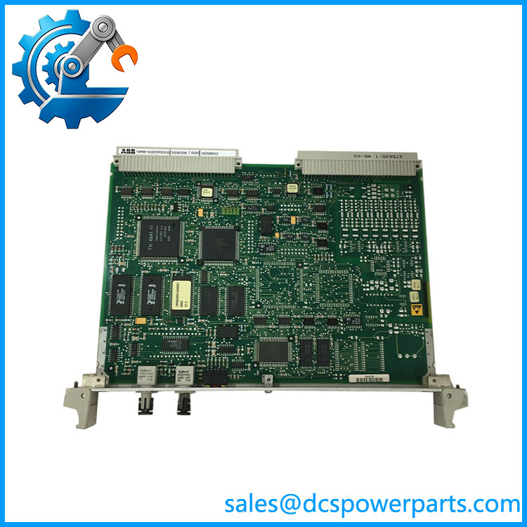
500MBA02-1MRB150003R000B
Key Features and Advantages
A processor of its own: MVB traffic does not compete with the application program’s execution time, because the bus controller is a separate processor rather than an interface hanging off the main CPU.
Deterministic separation of the three communication levels: LON for the station, optical RS 232 for the service PC, optical MVB for the process — each with its own interface and its own module, so a failure or a reconfiguration on one level does not disturb the others.
One fixed slot, no guesswork: the manual’s slot table gives 500MBA02 a single permissible position in the 21-slot rack, so mechanical assembly does not depend on a decision made at commissioning.
Correctly bounded to the basic rack: the extension rack is explicitly defined without processor, adapter and process controller modules, so the design keeps one bus master and reaches outward through the star coupler instead of multiplying controllers.
Optical process bus with usable reach: through 500SCM01, two fibre cores per bay unit at 62.5/125 µm, 5 dB maximum attenuation, approximately 1200 m — enough to place distributed I/O and intelligent sensors at the switchgear rather than in the relay room.
1 ms event resolution with time distribution over the station bus: sequence-of-events recording without a separate synchronization network, which is what substation event analysis actually requires.
A 3 W burden that keeps the supply budget honest: the REC 580 power budget is built from per-module figures — CPU 7 W, star coupler 3.5 W, analog input unit 6 W — and the bus controller’s 3 W is one of them rather than an allowance.
Applications
High-voltage substation bay automation: the native application, where a REC 580 controls one bay and the process bus carries commands and measurements to and from the switchgear.
Intelligent sensors and actuators at the primary equipment: PISA interfaces over MVB let optical voltage transducers and integrated actuators report digitally, which is the wiring reduction the process bus was designed for.
Distributed I/O in the switchgear: inputs and outputs that cannot live in the bay panel are reached over the optical process bus instead of being hard-wired back.
Rack expansion: where the basic rack’s 21 slots are insufficient, the extension rack is attached over MVB with 500MBA02 in the basic rack and 500AIM02 in the extension rack.
Retrofit and spare holding for REC 580 / PANORAMA installations: existing bays keep needing this module when a bus controller fails, and it is not interchangeable with the I/O modules around it.
Not applicable to a Procontrol P13/P14 I/O cage, and not a module for the extension rack — those are the two misapplications this part number attracts most often.
Related Products
500CPU03 — processor module and VME bus controller of the same rack; hosts the program and the two Industry Pack sockets. 500PBI01 — process bus interface for Industry Pack slot D of 500CPU03; the companion without which 500MBA02 has no data path. 500LBI02 — station bus LON interface for Industry Pack slot C, the counterpart on the station side. 500SCM01 — star coupler module converting electrical MVB signals to optical; provides the fibre path to extension racks and distributed I/O. 500AIM02 — analog input unit required in the extension rack when a second rack is attached over MVB. 500MBA01 — the adjacent release 1MRB150003R0002 at the same base block; not defined in the REC 580 manual and not interchangeable by assumption. 500PSM02 / 500PSM03 — auxiliary supply units, 60 W and 100 W from 36–312 V DC, which carry the burden this module adds. 500BIM01 / 500BOM01 — binary input and binary output modules of the same rack, placeable across the middle slots. 500CRB01 / 500CRB02 — the two backplanes whose slot tables govern where 500MBA02 may sit.
Installation and Maintenance
Before installation: identify the installed backplane — 500CRB01 or 500CRB02 — because the slot configuration tables differ between them, and place the module only in the position the table permits for that backplane. Confirm the basic rack rather than an extension rack is being equipped, since the extension rack carries no process controller modules. Check that 500PBI01 is present in Industry Pack slot D of the 500CPU03; without it the bus controller has no path into the CPU, and the fault will look like a bus problem rather than a missing card.
Installation: with the rack de-energised, seat the module and verify the rear MVB connection. Where an extension rack or distributed I/O is being attached, confirm the 500SCM01 star coupler and its fibre work are in place — two cores per bay unit, 62.5/125 µm, FST connectors, attenuation within 5 dB and length within approximately 1200 m — because the optical budget is the part of this bus that fails silently. Total the rack burden including the 3 W this module consumes, alongside CPU 7 W, star coupler 3.5 W and analog input unit 6 W, and confirm the 500PSM02 or 500PSM03 has headroom before adding further modules.
Maintenance: treat bus faults as two questions in order — is the data path complete (PBI01 seated, MVB connected), and is the optical link within budget. Record the module’s own order code from its label rather than from paperwork, because the release field is where transcription corrupts: 500MBA02 carries 1MRB150003R0003, while 1MRB150003R000B is a mis-keyed form of the same release and letters are not valid in that field of this numbering scheme. When replacing a module, confirm the replacement’s slot and backplane compatibility and re-check event time stamping to 1 ms after the exchange, since that is the function the bay’s sequence-of-events record depends on.
Warranty and Quality
Every 500MBA02 unit is supplied as the REC 580 process bus controller module, with the release field resolved to 1MRB150003R0003 and the form sent as 1MRB150003R000B identified as a transcription corruption rather than a separate part. Units are inspected for connector and backplane-edge condition, module latch and faceplate condition, label legibility at the order-code level, and for evidence of prior repair or rework. Technical data is quoted from ABB’s own REC 580 documentation — the Bay Control Terminal REC 580*3.0 manual, 1MRK 511 059-BEN — for the module’s official function (“has its own processor and controls the exchange of data via MVB”), its 3 W burden, its single fixed slot in the 21-slot rack under the 500CRB02 configuration table, the definition that extension racks carry no process controller modules, the requirement that 500CPU03 be fitted with 500PBI01 in Industry Pack slot D, the star coupler’s optical figures of two cores per bay unit at 62.5/125 µm, ≤5 dB and approximately 1200 m, the rack dimensions of 483 × 266 (6U) × 320 mm, and the 1 ms event time stamping with distribution over the station bus. Statements placing this module in a Procontrol P13/P14 rack or describing it as a bus coupling module are not adopted: the manual’s own function definition and its rack context are the basis here. A 12-month repair, replacement or refund commitment applies. Technical support covers the questions this part actually raises — backplane-specific slot placement, the PBI01 dependency, star coupler optical budget, rack power accounting, and reading the release field correctly when the label and the paperwork disagree.
免费
今天 11:41