Description
Moog G772K240 S38FOFA4V14 — Product Page
Product Overview
The Moog G772K240 S38FOFA4V14 is a two-stage electrohydraulic servo valve designed to regulate hydraulic flow in precision control applications. It belongs to Moog’s G77X servo-valve family, which uses a pilot stage with mechanical feedback to control the main hydraulic spool. By translating an electrical command into a corresponding hydraulic response, the valve enables a control system to position hydraulic actuators with the response and repeatability required by demanding industrial machinery.
In gas-turbine installations, servo valves of this type can form part of hydraulic actuator circuits used to regulate fuel-control equipment or other turbine mechanisms. The exact duty depends on the turbine package and hydraulic circuit design. Listings for the G772K240 associate it with GE drawing number 312A6077P003 and an electrical command range of −7.2 to +8.8 mA. These are important identification details, but the complete electrical and hydraulic requirements should be checked against the installed valve documentation before commissioning or replacement.
A servo valve’s condition affects more than whether an actuator moves. Internal contamination, spool wear, pilot-stage degradation, incorrect electrical command polarity, or unstable hydraulic supply conditions can cause sluggish response, hunting, position error, or failure to reach the commanded position. For that reason, replacing a Moog G772K240 should include checks of hydraulic fluid cleanliness, supply and return pressure, electrical command and feedback signals, actuator linkage, and the associated control loop. A replacement valve cannot correct a fault caused by contaminated oil or a defective actuator.
For procurement, verify the complete model and type code rather than ordering by the G772K240 family designation alone. Some suppliers list G772K240A as a successor to G772K240, but that listing alone does not establish interchangeability in every turbine package. Compare the mounting interface, port arrangement, electrical connector, command signal, pressure rating, and required dynamic response. If the valve is used in a turbine protection or fuel-control circuit, follow the OEM-approved replacement and commissioning procedure.
Product Introduction — Practical Field Focus
When a hydraulic actuator responds slowly, oscillates, or fails to follow its command, the servo valve is one possible source of the problem—but hydraulic contamination, unstable supply pressure, actuator wear, and control-signal faults must also be investigated. The Moog S38FOFA4V14 is a two-stage servo valve associated with industrial gas-turbine hydraulic control applications.
Before replacement, record the installed type code and electrical command range, confirm the hydraulic pressure and port configuration, and inspect the fluid cleanliness and return circuit. Following installation, verify actuator response and stability under the approved commissioning procedure.
Key Technical Specifications
| Parameter | Specification |
|---|---|
| Manufacturer | Moog |
| Model | |
| Type code | S38FOFA4V14 |
| Associated GE drawing number | 312A6077P003 |
| Product type | Electrohydraulic servo valve |
| Valve architecture | Two-stage, mechanical-feedback pilot stage |
| Product family | Moog G77X |
| Control input | Electrical current command |
| Reported command range | −7.2 to +8.8 mA |
| Reported pressure rating | 3,000 psi |
| Reported nominal port size | 5 mm for the referenced G77X configuration; verify exact unit |
| Controlled medium | Hydraulic fluid |
| Typical application | Industrial gas-turbine hydraulic control |
| Successor reported by suppliers | G772K240A; manufacturer confirmation required |
| Hydraulic fluid specification | Confirm against the applicable Moog data sheet and turbine OEM requirements |
| Mounting and port interface | Verify against the installed valve and drawing |
| Electrical connector and pinout | Verify from the nameplate and applicable wiring drawing |
| Dynamic response and flow characteristics | Confirm from the specific valve specification |
| Condition and service history | Check nameplate, inspection records, and test documentation |
Engineering note: The command range, pressure rating, and associated drawing number above come from application and spare-parts listings, not a verified current Moog technical datasheet for the exact serial-numbered unit. Do not use these values as final design limits without checking the original specification.
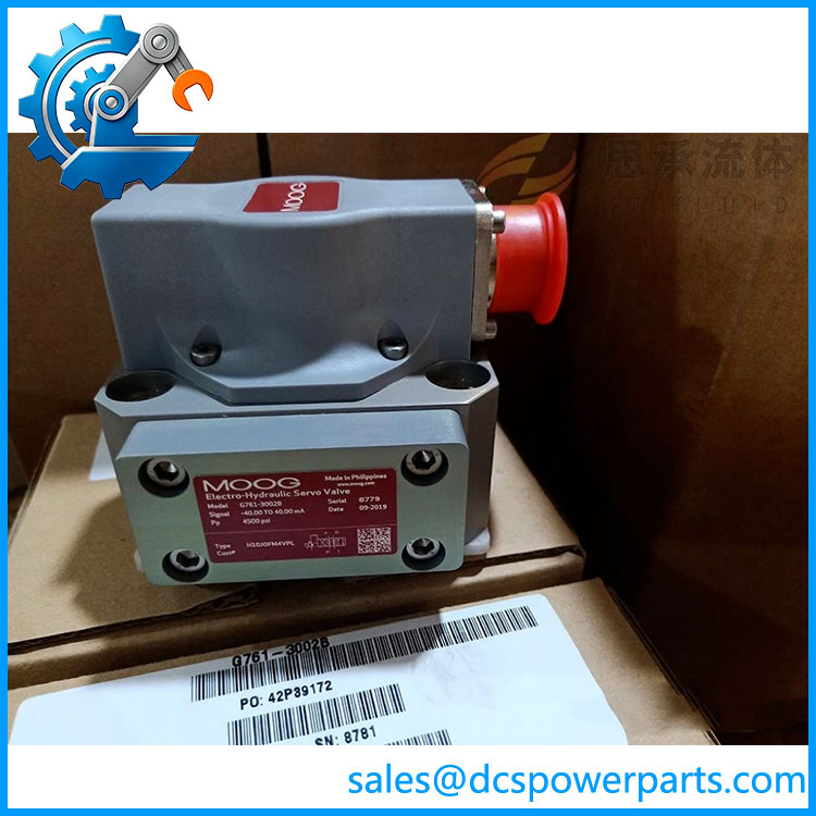
G772K240 S38FOFA4V14
Related Products
- Moog G772K240A — Listed by some suppliers as a successor to ; confirm the approved configuration before replacing the original valve.
- Moog G772K619 — Another G772-series servo valve appearing in turbine-control spare-parts listings; its type and application must be checked independently.
- Moog G772K620 — Related G772-series model listed for turbine hydraulic applications; not automatically interchangeable with .
- Moog G771K200A — G771-series servo valve with a different model designation and configuration.
- Moog G771K202A — Related G771-series servo valve used in industrial control applications.
- Moog G771K208A — Servo valve from the same broad product family, with a different type configuration.
- Moog G761-3039B — G761-series servo valve; a different design that should not be treated as a drop-in substitute.
- Moog G77X service and repair components — Suitable only when matched to the exact valve version and an approved repair procedure.
Frequently Asked Questions
Q1. What is the Moog S38FOFA4V14 used for?
It is a two-stage electrohydraulic servo valve used in industrial hydraulic control systems. Listings associate it with gas-turbine applications, including circuits identified by GE drawing number 312A6077P003.
Q2. What electrical command signal is associated with this valve?
Application-specific listings report a command range of −7.2 to +8.8 mA. Confirm this against the installed valve’s documentation and the control-system output configuration before connecting or testing it.
Q3. What is the hydraulic pressure rating?
Some spare-parts listings identify a 3,000 psi rating. Treat this as a preliminary identification detail only; verify the applicable Moog specification and turbine OEM documentation before operating the valve at that pressure.
Q4. Can be replaced with G772K240A?
Some suppliers list G772K240A as a successor to . Do not assume that the suffix change guarantees a direct replacement. Confirm the electrical command range, hydraulic characteristics, mounting dimensions, connector, and OEM approval for the specific application.
Q5. What can cause unstable actuator movement with this servo valve?
Potential causes include contaminated hydraulic fluid, spool or pilot-stage wear, air in the hydraulic circuit, unstable supply pressure, excessive return pressure, actuator friction, and incorrect electrical feedback or command signals. Check the entire hydraulic control loop before concluding that the valve itself has failed.
Q6. Can the servo valve be repaired in the field?
Repair suitability depends on the valve condition, the availability of approved service procedures, and the criticality of the application. Precision servo valves require controlled cleanliness and suitable test equipment. For turbine fuel or protection-related applications, use an authorized repair process and complete the required post-repair performance checks.
Q7. What should procurement verify before purchasing a replacement?
Request photographs of the complete nameplate, model and type code, serial number, connector and mounting interface, and any associated OEM part number. For used or refurbished units, request the test scope, hydraulic performance report, repair history, and warranty terms. A generic statement that the valve is “tested” does not establish that its dynamic response meets the original requirement.
Q8. What checks are required after installation?
Follow the turbine OEM procedure to verify hydraulic supply and return conditions, electrical command polarity and range, actuator travel, response stability, and the configured control-loop behavior. Do not introduce a replacement into a critical turbine circuit until its compatibility and functional performance have been confirmed.