Description
Moog G122-824-002 P-I Servo Amplifier
Product Introduction
In a hydraulic position loop, the PLC or controller usually does not provide the complete servo-loop function by itself. The command has to be conditioned, compared with feedback, amplified, and converted into a suitable drive signal for the valve. The Moog G122-824-002 is built for that job: it is a user-configurable P-I servo amplifier for closed-loop hydraulic control, with selectable proportional and integral operation. Moog’s own documentation identifies the -002 as the updated version of the G122-824-001.
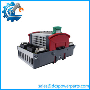
The revision is important when replacing an older amplifier. Moog added 4–20 mA capability at Input 2, an output-step push button for loop optimization, and improved thermal performance. The amplifier uses a compact DIN-rail enclosure and +24 V supply, with front-panel adjustment points, LEDs, and test points intended for commissioning and troubleshooting.
Key Technical Specifications
| Parameter | Specification |
|---|---|
| Manufacturer | Moog |
| Model | G122-824-002 |
| Series | G122-824 |
| Product Type | P-I Servo Amplifier |
| Control Architecture | Proportional, integral, or P + I |
| Primary Application | Closed-loop electrohydraulic control |
| Supply Voltage | +24 VDC |
| Input Configuration | Selectable analog signal configurations |
| Input Signal | 4–20 mA or ±10 V, depending on input/configuration |
| Input 2 | 4–20 mA capability added in -002 revision |
| Feedback Interface | Selectable 4–20 mA or ±10 V configuration |
| Output | Selectable current or voltage drive configuration |
| Dither | Selectable |
| Enable Function | Yes |
| In-Position Output | Yes |
| Feedback Excitation | Provided |
| Adjustment | Front-panel potentiometers, LEDs and test points |
| Mounting | DIN rail |
| Housing | Compact DIN-rail module |
| Revision | Functional replacement for G122-824-001 |
Moog’s application documentation describes the G122-824-002 as a general-purpose, user-configurable P-I servo amplifier. Internal selector switches determine whether proportional control, integral control, or both are used, while front-panel controls provide adjustment of loop characteristics.
The published documentation also identifies selectable feedback input and Input 2 configurations, output current/voltage selection, dither, enable input, feedback transducer excitation, and an in-position output.
Application Scenarios & Pain Points
The practical issue with this type of amplifier is loop compatibility. A replacement can have the correct model number and still require configuration changes if the feedback device, command signal, output stage, or P/I settings differ from the original installation.
Typical applications include:
- Hydraulic actuator position control: Closing a position loop around an electrohydraulic actuator using an LVDT or similar feedback device.
- Turbine hydraulic control: Moog specifically noted turbine applications as one reason for adding the 4–20 mA Input 2 capability to the -002 revision.
- Hydraulic governor systems: ABB hydro-power documentation shows the -002 used in a distribution-valve servo-control arrangement with LVDT feedback and associated current/voltage signal interfaces.
- Industrial motion and positioning: Suitable for applications where proportional/integral processing is required between a controller, feedback transducer, and hydraulic servo valve.
Field note: Do not treat the -002 as a generic analog output card. The module is configured around servo-loop behavior. Gain, integral action, feedback scaling, dither, output configuration, and enable logic can directly affect actuator stability.
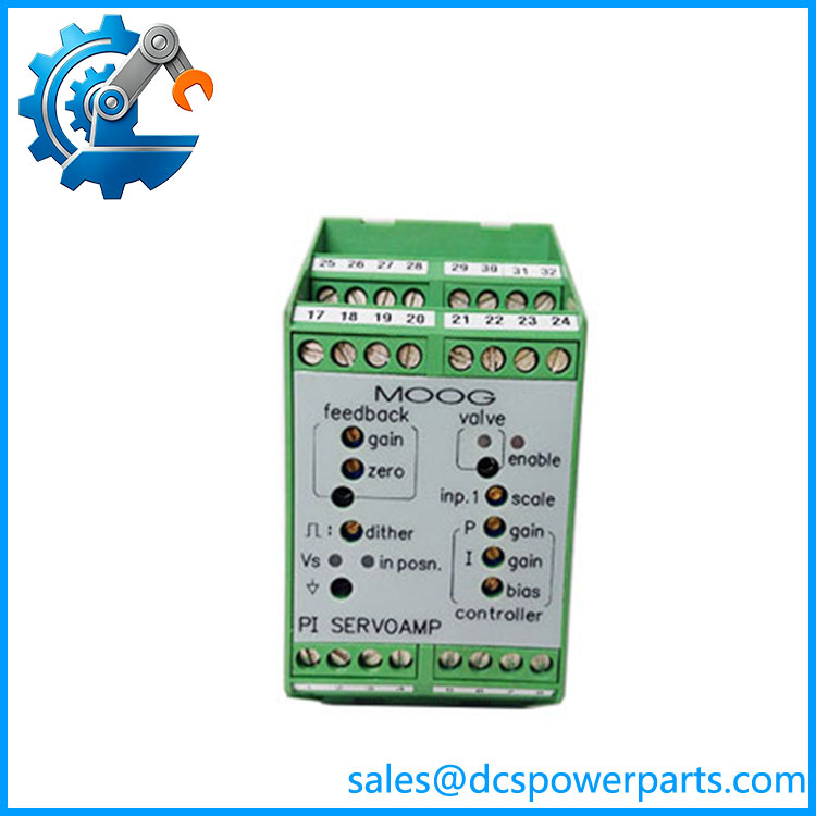
G122-824-002
Related Products
- Moog G122-824-001 — Earlier version of the amplifier. The -002 is its functional replacement and adds the 4–20 mA Input 2 option, output-step function, and improved thermal performance.
- Moog Series — Same servo-amplifier family; useful when checking legacy documentation and application notes.
- Moog D633K Series — Direct-drive proportional valve family commonly encountered in electrohydraulic control systems; valve selection must match amplifier output requirements.
- Moog D635K Series — Direct-drive proportional valve family used in higher-flow hydraulic control applications; signal and electrical configuration must be checked against the amplifier.
- ABB CC-U/STD — Signal-conditioning equipment that may appear in hydro governor architectures althe .
- LVDT Feedback Transducers — Position-feedback devices commonly usthe in hydraulic actuator loops.
The ABB hydro-power reference is particularly useful when reconstructing a legacy governor system because it explicitlthe in a distribution-valve servo loop with LVDT feedback.
Engineer’s Guide — Field Pitfalls to Avoid
1. Do not confuse the amplifier with the servo valve
The is the electronic P-I servo amplifier. It is not the hydraulic valve itself.
Avoidance: Confirm the complete loop: cr → → servo/proportional valve → hydraulic actuator → feedback transducer.
2. Verify the signal configuration before wiring
The amplifier supports selectable signal arrangements, including 4–20 mA and ±10 V configurations. The actual switch and resistor configuration matters.
Avoidance: Photograph or document the internal selector settings of the existing unit before replacement. Do not assume that a terminal marked as an input automatically accepts the signal range you intend to apply.
3. The -002 revision is not simply cosmetic
Moog specifically states that the -002 replaced the -001 and introduced three functional improvements: 4–20 mA at Input 2, an output-step push button, and improved thermal performance.
Avoidance: When replacing a -001, review the old application notes and verify the new configuration rather than transferring every jumper position blindly.
4. Do not copy P/I settings without checking actuator behavior
Gain and integral settings are part of the hydraulic control loop. A setting that worked on one actuator, valve, or feedback arrangement may produce oscillation or sluggish response on another.
Avoidance: Commission the loop with the hydraulic system in a controlled state. Check zero, gain, integral response, feedback scaling, and dither before applying full operating demand.
5. Verify the feedback transducer
The feedback path is just as important as the commandThe documentation provides for feedback signal selection and transducer excitation.
Avoidance: Confirm feedback type, polarity, scaling, excitation requirements, and mechanical travel before energizing the loop.
6. Check DIN-rail wiring and service access
The amplifier is designed as a DIN-rail module with screw terminals, and the application notes specifically discuss allowing enough cable length to withdraw the circuit card from its enclosure for switch changes.
Avoidance: Do not bundle the wiring so tightly that internal configuration or troubleshooting requires disconnecting the entire control loop.
FAQ
What oog ?
It is a general-purpose P-I servo amplifier designed for closed-loop control applications. It can provide proportional control, integral control, or combined P + I operation.
Is a PLC module?
No. It is a dedicated analog servo amplifier. Although it can interface with a PLC, DCS, governor controller, or other automation controller, its purpose is to perform servo-loop processing and valve-drive functions rather than general-purpose logic or I/O.
What power oes require?
The published Moog documentation specifies a +24 VDC supply.
What is the difference betweand ?
The -002 is the functional replacement for the -001. Moog identifies three changes: 4–20 mA capability on Input 2, an output-step push button for loop optimization, and improved thermal performance.
Can accept a 4–20 mA command?
Yes, the -002 revision specifically added a 4–20 mA option for Input 2. Other input and feedback configurations are selectable, so the actual wiring and internal configuration still need to be checked.
Can it be used with an LVDT?
The is suited to closed-loop hydraulic position control using a feedback transducer, and an ABB hydro-power application explicitly documents the amplifier in a distribution-valve loop using LVDT feedback.
What should be checked before purchasing a replacement?
Verify the act part number, internal switch/jumper configuration, command signal type, feedback signal type, output configuration, P/I settings, supply voltage, and physical condition. For a working hydraulic loop, configuration is part of the functional identity of the amplifier—not just the label on the front.