Description
Moog D633K2016C
Product Introduction
In a hydraulic power unit, a proportional valve failure can look like a controller problem: the command is present, but actuator position or pressure no longer follows the expected response. The Moog D633K2016C is a D633K-series direct-drive proportional valve with integrated electronics, designed to translate a bipolar electrical command into precise hydraulic spool movement. Available technical information identifies the valve with a 24 VDC supply, ±10 mA command interface, and approximately 8 L/min nominal flow at a 5 bar pressure drop per land.
The D633K2016C is particularly relevant to established hydraulic control systems where the original ±10 mA interface and valve characteristics must be preserved. That signal specification is a procurement-critical detail: a later valve using a 4–20 mA interface is not automatically a replacement simply because the mounting arrangement looks similar. The D633K and D635K families use different control architectures, so any HPU retrofit should be evaluated as a complete valve-and-electronics compatibility problem rather than a mechanical substitution.
Key Technical Specifications
| Parameter | Specification |
|---|---|
| Product Model | D633K2016C |
| Manufacturer | Moog |
| Product Series | D633K |
| Product Type | Direct-drive proportional valve |
| Electronics | Integrated valve electronics |
| Supply Voltage | 24 VDC |
| Command Signal | ±10 mA |
| Nominal Flow | Approx. 8 L/min |
| Reference Pressure Drop | 5 bar per land |
| Control Principle | Direct-drive proportional spool control |
| Hydraulic Application | Position, speed, pressure, or force control |
| Fail-Safe Position | Spool moves toward center on power-down |
| Electrical Connection | 6+PE pin connector |
| Connector Standard | DIN 43651 type |
| Typical Application | Hydraulic power units, servo-hydraulic machinery, industrial motion control |
| Series Family | Moog D633K / Series 30 |
The 8 L/min value is associated with the specific D633K2016C configuration found in available technical listings. Do not generalize that flow rating to every D633K valve; Moog D633 variants are available with different hydraulic specifications.
Application Scenarios & Pain Points
A D633K replacement should be approached from the hydraulic and electrical sides simultaneously. The valve’s command interface, spool characteristics, flow rating, and integrated electronics all affect how the actuator responds.
- Hydraulic power units: Provides proportional flow control for hydraulic actuators where command accuracy and dynamic response are important.
- Servo-hydraulic machinery: Appropriate for systems requiring controlled actuator position, velocity, pressure, or force.
- Industrial motion control: The direct-drive arrangement can provide rapid spool response without relying on a conventional pilot stage.
- Legacy HPU maintenance: Useful where an existing control system was engineered around a bipolar ±10 mA interface.
Field note: Before changing the valve, measure the actual command signal with the controller operating under a safe test condition. If the system expects ±10 mA and the replacement expects 4–20 mA, the problem is not solved by changing only the hydraulic body.
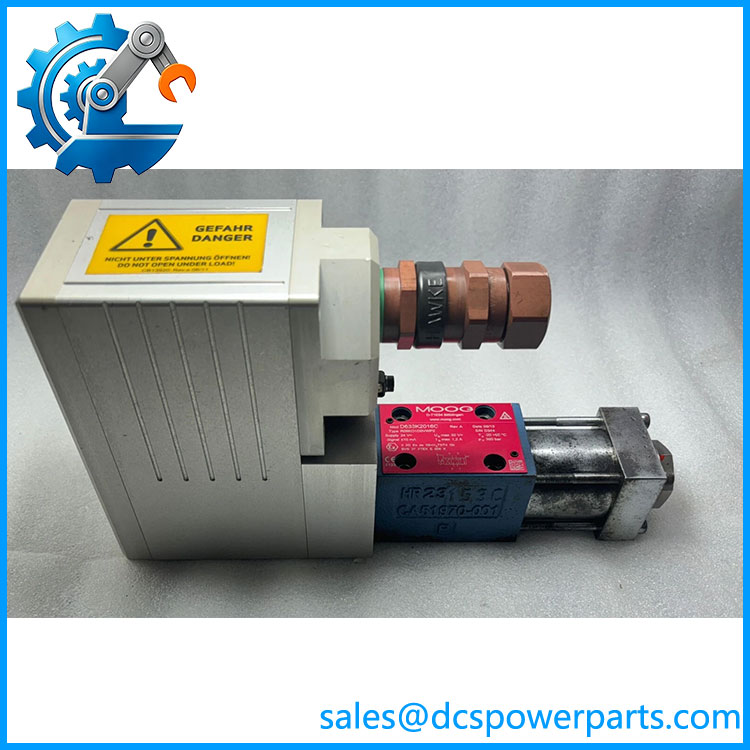
D633K2016c
Related Products
- Moog Series — Same direct-drive proportional-valve family; exact flow, spool, and electrical configuration must be matched.
- Moog D633K2016C R08KO1D0VWP2 — A detailed configuration reference associated with , including an 8 L/min hydraulic specification.
- Moog D635K2022E — Related proportional-valve family with a different electrical control interface; available evidence identifies it with 4–20 mA rather than the ±10 mA interface.
- Moog D633 Series — Broader D633 direct-drive proportional-valve family with multiple flow and configuration options.
- Moog D635 Series — Related proportional-valve family, but substitution requires a complete electrical and hydraulic compatibility review.
The D635K2022E should not be treated as a drop-in replacement. The documented signal difference alone is sufficient to require a detailed controls review before considering a substitution.
Engineer’s Guide — Field Pitfalls to Avoid
Pitfall 1: Confusing ±10 mA with 4–20 mA
The uses a bipolar ±10 mA command. This is fundamentally different from the unipolar 4–20 mA interface used by certain D635K configurations.
Avoidance: Verify the analog output card, signal polarity, scaling, zero point, and full-scale command before energizing the replacement.
Pitfall 2: Replacing only the hydraulic section
The integrated electronics and hydraulic section are part of the valve’s operating characteristics. A mechanically similar hydraulic section from another series should not be assumed compatible.
Avoidance: Match the complete Moog configuration, including electronics, spool configuration, flow rating, and command interface.
Pitfall 3: Ignoring zero position
A proportional valve can appear electrically functional while having an incorrect null position or excessive offset. That can produce actuator creep or unstable closed-loop behavior.
Avoidance: Record the existing null behavior and follow the applicable Moog commissioning procedure after replacement.
Pitfall 4: Treating the connector as the only compatibility criterion
A matching connector does not establish hydraulic compatibility. Flow rating, pressure drop, spool characteristic, command signal, and actuator requirements still have to match.
Avoidance: Compare the complete valve ordering code and hydraulic schematic.
Pitfall 5: Buying by “” alone
identifies the family, not the complete valve configuration.
Avoidance: Specify in procurement documents and request the actual nameplate, complete ordering code, electrical-interface information, and calibration/test status.
FAQ
What is the Moog ?
The is a direct-drive proportional hydraulic valve with integrated electronics. It is designed for dynamic control of hydraulic flow and actuator movement.
What control signal does use?
Available documentation identifies the with a ±10 mA bipolar command signal and a 24 VDC supply.
What is the nominal flow rating?
The documented configuration has a nominal flow of approximately 8 L/min at a 5 bar pressure drop per land. The exact flow specification should be verified against the complete valve ordering code on the installed unit.
Is a servo valve or proportional valve?
It is commonly described as a direct-drive proportional valve (DDV) with integrated electronics. Its function is proportional hydraulic control, making it suitable for servo-hydraulic applications where closed-loop control of position, speed, pressure, or force is required.
Can D635K2022E replace ?
Not as a direct substitution. Available technical comparisons identify the with ±10 mA control and the D635K2022E with 4–20 mA control. The two families also have different electronic and hydraulic architectures.
What should I verify before purchasing a replacement?
Verify the complete ordering code, command signal, 24 VDC supply, nominal flow, pressure rating, spool configuration, electrical connector, mounting dimensions, and actual calibration/test condition. For a working HPU, also compare the valve specification with the hydraulic schematic and controller output configuration.
Does the valve require calibration after replacement?
The replacement should be commissioned according to the applicable Moog procedure and the site’s hydraulic-control requirements. In particular, verify null position, command scaling, actuator direction, feedback response, and maximum commanded flow before returning the HPU to normal operation.