Description
Product Overview
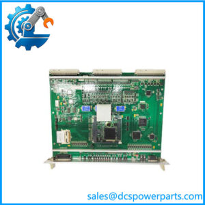
VLE 12004-101-01 V1.1.0 is the board that explains the rest of its block. Every other card covered in this family carries a function code starting at 102 — the VPS supply, the I/OBUS2 bus interface at 103, the I/OBE2 extender at 104, the VOOB8-B output module at 106. The 101 slot was the one code nobody had filled, and it is filled by the core processor. Read as a sequence, the block now makes architectural sense in the way a cabinet drawing does: the logic core sits first, its power supply sits immediately behind it, the bus interface carries its I/O traffic, the extender pushes that traffic beyond the chassis, and the I/O cards at the far codes terminate the field. A card numbered before the power supply is not an I/O card; it is the thing the supply exists to feed.
That reading is corroborated by the one published account of this board that holds together. A Chinese supplier describes it as the 12004 rack’s main processing and interlocking core, built around two independent processors that execute safety logic in parallel and cross-check each other through dual-port memory, communicating with the I/O bus and with a system maintenance and diagnostics function — the cabinet’s brain rather than a field interface. That is exactly the architecture a vital interlocking core would have: two channels executing the same logic and a comparator that refuses to proceed when they disagree. It is supplier-stated, not documented, but it is internally coherent, consistent with the board’s position in the block, and consistent with the way another supplier describes the bus interface as bridging the VLE board to the I/O boards.
The rest of the market does not hold together at all. One seller calls it a controller module for power systems and rail transit. Another calls it a communication interface module doing multi-protocol conversion. A third gives it 16 digital inputs and 16 digital outputs at 24 VDC with Ethernet, RS-232 and RS-485 — and that same seller, on a second page for the identical part number, gives it 32 inputs and 32 outputs. A fourth files it as a multi-analogue-output module at a list price of ten thousand dollars discounted to one thousand and fifty. A fifth gives it 220 V AC, a 50 kHz output frequency, CE, UL and ISO 9001, and names the manufacturer as “Global Industrial Components”. A board cannot be simultaneously a core processor, a protocol converter, a 32-point I/O card, an analogue output module and a mains-powered unit with a kilohertz output. Three of those are templates; one of them is a template with a price attached.
What survives is the architecture, and this board is where the whole family’s platform question finally tilts. I/OBUS2 has been described by one seller as part of Alstom’s iLOCK computer-based interlocking bridging the VLE board and the I/O boards, and the coherent account of VLE itself is filed under iLOCK and legacy DCS. Two sources that disagree about almost everything else agree that a VLE board sits at the centre and a bus board fans out to the I/O. That moves the balance of evidence toward a railway interlocking cabinet rather than a power-station DCS rack — though “iLOCK” is a trade label, not a name that appears among Alstom’s published interlocking families, which are Smartlock 400 GP and Onvia Lock. One listing even gives Sweden as the country of origin, which would fit a Nordic signalling provenance better than a French power-automation one. None of this is documentation; all of it points the same way.
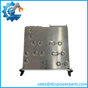
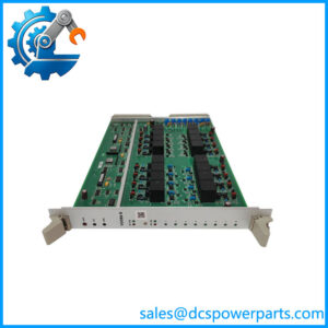
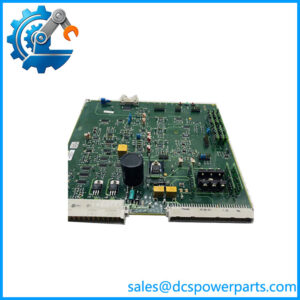
The physical description is therefore the only safe ground: a plug-in processor board for the 12004 rack, backplane-powered, with no field termination of its own, marked with a revision, replaced by cold swap. Its value in a plant is not its electronics but the logic image and configuration that give it a job — a fact that changes how a spare should be held and how a swap should be planned.
Technical Specifications
| Parameter | Value |
|---|---|
| Model designation | VLE |
| Order number | 12004-101-01 |
| Revision | V1.1.0 |
| Manufacturer | Alstom (legacy control rack line; power automation transferred to GE, 2015) |
| Product type | Rack core processing / interlocking logic board — no field I/O |
| Position in block | Function code 101, the lowest in the 12004 block, ahead of VPS 12004-102-01 |
| Architecture (supplier-stated) | Two independent processors executing safety logic in parallel with cross-check through dual-port memory; links to I/O bus and to system maintenance diagnostics |
| Bus interface | Communicates to the I/O bus through I/OBUS2 12004-103-01; segment extension through I/OBE2 12004-104-00 |
| Rack format | Plug-in card, card guides, captive screws, backplane connector |
| Power supply | From the rack backplane, fed by VPS 12004-102-01; no external supply input on the board |
| Field termination | None — no front-panel field wiring; status indication only |
| Operating environment | Ventilated control cabinet, typically 0 to +55 °C; IP20 cabinet interior |
| Replacement method | Cold swap with rack de-energised; application logic and configuration must be preserved |
| Published documentation | None — no Alstom or GE board-level datasheet, no processor specification |
| Lifecycle status | No OEM end-of-life notice located; supply is dismantled and refurbished stock |
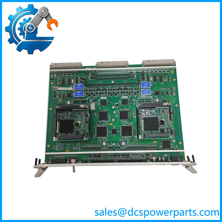
VLE 12004-101-01 V1.1.0
Key Features and Advantages
A block that reads as a cabinet: with VLE at 101, the 12004 function codes now describe a complete architecture — core, supply, bus interface, extender, I/O. That is the single most useful thing about this part number, because it lets an engineer reconstruct a cabinet from numbers when the drawings are gone.
Core rather than interface: the board has no field terminals, no channel count and no output stage. Everything it does happens on the backplane, which means its failure presents as a silent loss of logic or a diagnostic stop rather than as bad channel data — a diagnosis that determines whether the plant looks at the field or at the cabinet.
Dual-channel logic with comparison: if the supplier account is accurate, the board runs the same logic twice on independent processors and cross-checks through shared memory. That is the architecture a safety-critical interlocking requires, and it explains the board’s cost and the vendor’s insistence that it is not a field I/O card.
The logic image is the real asset: a replacement VLE 12004-101-01 V1.1.0 arrives as hardware. What makes it a working core is the application, its configuration and the revision they were built against. Recognising that turns a swap from a hardware purchase into a data-preservation exercise, which is where the real risk sits.
Revision per board, not per cabinet: this family carries mixed versions — V1.1.0 here, V1.20 on I/OBUS2, V1.0.0 on I/OBE2 and VOOB8-B. A cabinet is therefore never “at” one version, and each board must be matched against its own recorded revision rather than against a cabinet-level label.
Honest limits: the dual-processor account is supplier-stated, the platform attribution leans interlocking but is not documented, and every channel count, protocol and mains-voltage figure attached to this number in the market belongs to a template. Nothing above is invented to fill a datasheet.
Applications
Electronic interlocking cabinets: route locking, aspect control and point machine commands are executed in the interlocking core, and a board of this class is where those decisions are made. In that service its failure is a signalling restriction, not a process deviation, and the swap procedure has to reflect that.
Safety-logic evaluation with dual-channel comparison: where a cabinet is required to compare two independent executions of the same logic before acting, the core board is the element that performs the comparison. That architecture is what the supplier describes here, and it is why the board is not interchangeable with an I/O card of the same rack.
Legacy DCS rack cores: the same board is filed by another source under a legacy DCS interpretation, and in that reading it is the control core of a plant cabinet — the processor that the I/O cards and the bus serve.
Cabinet reconstruction from numbers: where drawings are missing but the rack is populated, reading the block as a sequence — 101 core, 102 supply, 103 bus, 104 extender — lets a maintenance team infer the architecture before opening anything.
Spares strategy for a discontinued rack: a core board is the one card whose absence stops the whole cabinet, and its supply is dismantled stock. Holding one verified board, with its logic image and configuration documented, is a different decision from holding I/O cards.
Where it does not fit: 16-point or 32-point I/O duty, analogue output duty, protocol conversion, DIN-rail mounting, 220 V AC mains supply, or any application described by a channel count. Those are the descriptions this number attracts, and none of them describes a processor board with no field terminals.
Related Products
I/OBUS2 12004-103-01 — the I/O bus interface board that carries this core’s traffic to the I/O cards; the closest functional partner in the block. I/OBE2 12004-104-00 — the bus extender paired with I/OBUS2; relevant where the core’s segment crosses a chassis boundary. VPS 12004-102-01 — the supply board immediately behind this core in the block; the source of the backplane rails the processor runs on. VOOB8-B 12004-106-04 — eight-channel output module at the far end of the block; the field-side counterpart of the core. VIIB16-C 12011-105-00 — 16-channel input module in the parallel 12011 block; a different number block, not a substitute. SDK-C0167-1 12004-08-01 — another board of the 12004 family whose code sits outside the -10x- sequence, showing how uneven this numbering really is. CMP1838 TRVCO62345000 / CP00005202 — ALSPA-generation rack control board from the same engineering culture; a three-layer designation rather than a block code.
Installation and Maintenance
Before installation: preserve the software before touching the hardware. Obtain the current logic image, its configuration and the revision it was built against, and confirm that a replacement VLE 12004-101-01 V1.1.0 is at the revision the site records — a core board at the wrong revision is a compatibility question, not a spare. Confirm the slot, the backplane keying and the connector condition, and photograph the populated rack so the board’s position is documented independently of a label. De-energise the rack completely; this generation is cold-swap only, and a processor board inserted into a live backplane risks both the card and whatever state the cabinet was holding.
Installation: seat the card to full backplane engagement along its guides and tighten the captive screws evenly, since a partially seated core produces exactly the kind of intermittent fault that gets blamed on the logic. On power-up, allow the rack to reach a stable state and read the diagnostics through the maintenance function before loading or trusting the application — a core that starts but reports internal disagreement needs to be stopped, not persuaded.
Maintenance: treat the logic image, the configuration record and the board revision as three parts of one asset, stored together and updated together; this is the maintenance work that keeps a spare meaningful. Keep the cabinet’s air path clean and its backplane connectors free of oxidation, since a core board’s most common false diagnosis is a bus or supply problem underneath it. Do not re-seat working cards as routine practice, and store a spare VLE board in dissipative packaging labelled with its part number and revision, alongside the media or records that hold the application it is meant to run.
Warranty and Quality
Every VLE 12004-101-01 V1.1.0 board is supplied as the core processing board of the Alstom 12004 rack and is documented by designation, order number and revision, so that it can be matched against a cabinet record and a slot. Units are inspected for backplane connector condition and pin integrity, card-edge and guide wear, captive screw function, PCB damage, rework evidence and corrosion, and for label legibility; verification covers power-up presence and self-test behaviour in a compatible rack where one is available. No processor architecture, channel count, protocol or mains specification is asserted, because the published descriptions for this number span a dual-processor interlocking core, a 16-point I/O card, a 32-point I/O card, a multi-analogue output module and a 220 V AC unit — and only the first is consistent with the board’s position in its own numbering block. A 12-month repair, replacement or refund commitment applies. Technical support covers what this part actually requires: explaining why function code 101 in front of the VPS supply identifies a core rather than an I/O card, why the logic image and revision must be preserved before any swap, and why a cabinet of this generation runs each board at its own revision rather than one cabinet-wide version.