Description
Key Technical Specifications
| Parameter | Reported specification |
|---|---|
| Product Model | G403-552A |
| Manufacturer | MOOG |
| Product Type | Three-stage electro-hydraulic servo valve |
| Control Signal | ±10 VDC differential |
| Rated Flow | 55 GPM / 208 L/min |
| Flow Test Pressure Drop | 1,000 psi / 70 bar |
| Maximum Working Pressure | 3,000 psi / 210 bar |
| Frequency Response | ≥80 Hz reported |
| Hysteresis | Below 1.5% reported |
| Feedback | LVDT; configuration requires verification |
| Hydraulic Fluid | Mineral hydraulic oil reported |
| Mounting | Manifold mounting; exact interface unconfirmed |
| Operating Temperature | Not confirmed by OEM documentation |
| Electrical Connector | Not confirmed |
These figures come from secondary product descriptions, not a verified MOOG technical datasheet. They must not be treated as approved engineering limits without confirmation.
Product Introduction
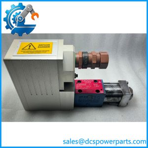
The MOOG G403-552A is listed as a three-stage electro-hydraulic servo valve for applications requiring precise control of hydraulic flow and actuator movement. In this type of control system, an electrical command signal regulates the valve’s internal hydraulic stages, allowing controlled adjustment of actuator position, speed, or force. Such equipment is commonly associated with industrial test systems, high-force machinery, and other closed-loop hydraulic applications.
The reported ±10 VDC command interface and 55 GPM flow rating indicate a high-capacity hydraulic control application. However, the precise valve architecture, rated flow conditions, feedback arrangement, and mounting dimensions require confirmation from the original equipment documentation. The conflicting servo-motor descriptions make nameplate verification particularly important before procurement.
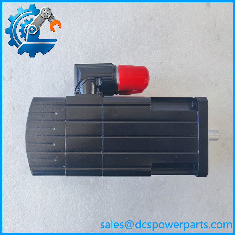
G403-552A
Major Features and Advantages
Three-stage hydraulic control
The reported three-stage construction uses multiple hydraulic amplification stages to regulate the main flow-control element. This arrangement is intended for applications requiring high flow capacity and precise command response.
Analog command interface
The reported ±10 VDC input allows integration with compatible analog servo controllers. Signal polarity, command scaling, and electrical grounding must be checked before commissioning.
High-flow capability
The secondary listing specifies 55 GPM at a 1,000 psi pressure drop. Actual flow depends on the specified test conditions and hydraulic circuit design.
Closed-loop positioning potential
An LVDT feedback arrangement is reported for certain configurations. Confirm whether the specific unit includes internal position feedback and whether the controller supports its electrical characteristics.
Hydraulic system integration
Correct manifold porting, pressure supply, return-line configuration, and fluid cleanliness are essential to valve performance.
Application Scenarios and Field Pitfalls
Potential applications include:
- Industrial hydraulic actuator control.
- High-force positioning equipment.
- Hydraulic test and simulation systems.
- Precision force and displacement control.
- Closed-loop machinery requiring proportional hydraulic flow regulation.
Before installation, verify:
- Complete valve nameplate and revision.
- Hydraulic port configuration and manifold dimensions.
- Rated pressure and flow requirements.
- Command signal polarity and input characteristics.
- LVDT feedback wiring, if fitted.
- Hydraulic fluid specification and filtration requirements.
- Controller gain and feedback calibration.
Field warning: Contaminated hydraulic oil can cause spool sticking, unstable control, and premature internal wear. Flush the hydraulic circuit and verify filtration before installing a replacement valve. Never remove the valve while the hydraulic system remains pressurized.
Related Products and Variants
Secondary listings identify the following related models:
- G403-550A
- G403-551A
- G403-553A
- G403-554A
- G403-555A
- G403-556A
- G403-557A
- G404-601A
These are related model designations, not confirmed direct replacements. Flow capacity, mounting, pressure rating, and electrical configuration must be compared individually.
Procurement and Quality Control
For a G403-552A replacement, request:
- Actual nameplate photographs.
- Hydraulic port and mounting-interface photographs.
- Electrical connector and pinout information.
- Flow-gain and hysteresis test results.
- Frequency-response test report, where applicable.
- LVDT feedback verification, if fitted.
- Hydraulic leakage and internal contamination inspection.
- Confirmation of new, used, or refurbished condition.
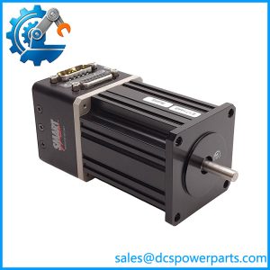
Engineering recommendation: Treat G403-552A as a MOOG hydraulic servo valve only after confirming the physical unit. Do not accept the servo-motor identification found in some supplier records as interchangeable with the valve identification. The complete nameplate and hydraulic port arrangement are the most useful evidence for resolving the discrepancy.