Description
Key Technical Specifications
| Parameter | Specification | Verification Notes |
|---|---|---|
| Model | G771K293A | Match the complete nameplate code |
| Manufacturer | MOOG | Manufacturer identification |
| Product Type | Electrohydraulic servo valve | Catalog-listed description |
| Series | G771 | Confirm against the original equipment documentation |
| Valve Design | Two-stage | Series-level description |
| Torque Motor | Dry torque motor | Confirm exact construction for the ordered variant |
| Pilot Stage | Double-nozzle pilot stage reported for the G77X family | Verify against the applicable technical data sheet |
| Control Signal | Analog electrical command | Exact current/voltage range is not confirmed here |
| Hydraulic Function | Direct-operated flow control | Supplier catalogs use this description |
| Rated Flow | Not confirmed | Must be selected against system flow demand and pressure drop |
| Maximum Operating Pressure | Not confirmed | Obtain the model-specific OEM rating |
| Internal Leakage | Not confirmed | Check the applicable performance curve and test conditions |
| Response / Frequency Characteristics | Not confirmed | Obtain model-specific dynamic data |
| Null Bias | Field-adjustable feature reported for the series | Adjust only using the OEM procedure |
| Hydraulic Fluid | Application-dependent | Verify fluid type, viscosity, temperature, and seal compatibility |
| Mounting Interface | Not confirmed for this exact code | Check port pattern, mounting dimensions, and seal arrangement |
| Electrical Connector | Not confirmed | Verify connector type and pinout |
| Operating Temperature | Not confirmed | Refer to the applicable data sheet |
| Replacement Cross-Reference | G771K202A and G771K242A | Secondary catalog references; confirm with MOOG before installation |
Public listings support the product identity, two-stage design, analog control, and replacement references, but do not establish a complete set of model-specific hydraulic ratings. Do not use unverified flow, pressure, or electrical values for engineering calculations.
Product Introduction
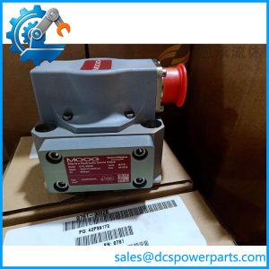
The MOOG G771K293A is a G771-series electrohydraulic servo valve intended to regulate hydraulic flow in response to an electrical command. Its two-stage design uses a torque-motor pilot stage to control the main spool, allowing the valve to regulate actuator movement in systems that require controlled hydraulic response. Product listings identify it as a replacement for G771K202A and G771K242A, but the final selection must account for the original valve’s flow rating, pressure conditions, command signal, and mounting configuration.
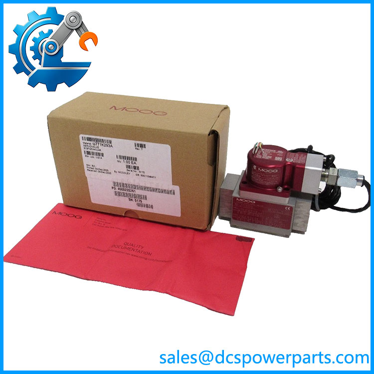
G771K293A
Application Scenarios & Field Pitfalls — The Engineer’s Perspective
Engineering Pain Point
Servo-valve replacement problems often appear as actuator instability, sluggish response, excessive null offset, or failure to hold position. These symptoms do not automatically mean the replacement valve is defective. Hydraulic contamination, incorrect command scaling, pressure imbalance, air in the circuit, and differences in valve characteristics can produce similar behavior.
Typical Applications
- Closed-loop hydraulic actuator control: Modulating flow to regulate actuator position, speed, or force under a feedback controller.
- Industrial machinery maintenance: Replacing a failed servo valve after confirming hydraulic and electrical compatibility.
- Legacy equipment support: Evaluating the G771K293A where the installed valve is identified as G771K202A or G771K242A.
- Hydraulic performance recovery: Investigating unstable motion, slow response, or null-position drift as part of a complete hydraulic-system diagnostic process.
These are general application categories for electrohydraulic servo valves; confirm the actual machine application and valve duty from its engineering documentation.
Technical Pitfalls to Avoid
- Do not substitute on part-number similarity alone. The published replacement relationship is a useful reference, not a substitute for checking the equipment manufacturer’s approved parts list.
- Confirm the electrical command interface. Check whether the controller drives the valve using the required current or voltage signal, and verify polarity, connector pinout, grounding, and cable shielding.
- Match the hydraulic performance envelope. Confirm rated flow, pressure drop, supply pressure, return pressure, and required response characteristics. A valve that physically fits may still provide the wrong flow gain or dynamic behavior.
- Control fluid contamination. Servo valves have precision pilot-stage clearances. Check filtration, flush the circuit where required, and investigate contamination before installing a replacement; otherwise, a new valve may fail prematurely.
- Verify mounting and port sealing. Compare the mounting pattern, port locations, O-rings or seals, and fastener requirements against the original valve. Do not assume that all G771 variants share every mechanical detail.
- Set null bias carefully. If adjustment is required, follow the OEM procedure and monitor the actual actuator feedback. Incorrect adjustment can cause unwanted movement or poor closed-loop performance.
- Check the control loop before blaming the valve. Review feedback polarity, controller tuning, command scaling, and actuator mechanics. A valve replacement can expose an existing tuning or instrumentation problem.
- Commission under controlled conditions. Follow the machine’s hydraulic isolation and startup procedures. Where practical, verify leakage, neutral behavior, command response, and stability at low risk before returning the equipment to normal duty.
Related Products and Model References
The following models are relevant for identification or cross-reference. They are not all interchangeable.
- MOOG G771K202A — Listed as a replacement predecessor for G771K293A. Verify the original valve’s complete configuration before substitution.
- MOOG G771K242A — Also listed as a replacement predecessor for G771K293A; confirm the equipment-specific approval and performance requirements.
- MOOG G771K289A — Listed in secondary cross-reference material as a replacement for G771K200A and G771K240A, not as a universal substitute for G771K293A.
- MOOG G771K287A — Listed as a replacement for G771K201A and G771K241A. Check its exact configuration before considering it.
- MOOG G771K291A — Listed as a replacement for G771K203A; not confirmed as a substitute for .
- MOOG G771K294A — Listed as a replacement for G771K208A and G771K244A; confirm flow and electrical characteristics before comparison.
Procurement Note
When purchasing MOOG , request photographs of the nameplate, connector, mounting face, and any visible damage. Require the supplier to disclose whether the valve is new, unused stored, repaired, or used. For repaired units, request the test scope and results rather than accepting a generic “tested” statement.
Before installation, confirm:
- The original valve part number and equipment-approved replacement status.
- Electrical command type, range, polarity, and connector pinout.
- Rated flow, pressure limits, and hydraulic fluid requirements.
- Mounting dimensions, port configuration, and seal specification.
- Null-bias and commissioning procedures.
- Test evidence, warranty terms, and return conditions.
Engineering recommendation: Treat as a configuration-specific servo valve, not a universal G771 replacement. Confirm the electrical interface and hydraulic performance data against the installed application before approving the substitution.