Description
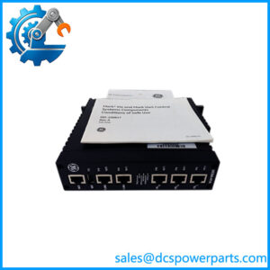
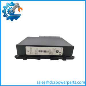
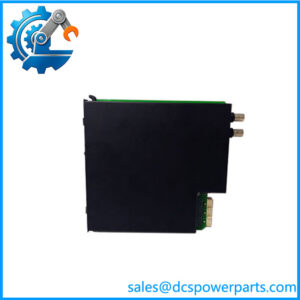
GE Multilin UR8CH CT/VT Module
Key Technical Specifications
| Parameter | Specification |
|---|---|
| Product Model | UR-8CH |
| Manufacturer | GE Multilin |
| Product Family | Universal Relay |
| Product Type | CT/VT Module |
| Phase CT Inputs | 3 × 1 A / 5 A |
| Ground CT Input | 1 × 1 A / 5 A |
| System Role | Current-transformer signal interface and measurement |
| Installation | UR Series relay chassis |
| Relay Interface | Internal UR platform connection |
| Application | Protection and electrical-system measurement |
| Approx. Dimensions | 6 × 7 × 1.5 in |
| Approx. Weight | 1.15 kg |
| Hardware Generation | Legacy UR module; exact compatibility depends on relay CPU and firmware |
The 3-phase and ground CT input ratings are consistently identified in the more specific technical references. The published physical dimensions and weight should be treated as approximate rather than cabinet-design dimensions.
Product Introduction
The GE Multilin is a CT/VT measurement module designed for compatible GE Multilin Universal Relays. Its primary purpose is to bring standardized transformer-secondary current signals into the relay’s measurement and protection architecture. The module provides three phase CT inputs rated for 1 A or 5 A secondary circuits together with a 1 A/5 A ground CT input, allowing the associated UR relay to process current information required for protection and monitoring functions.
The is a plug-in component of the UR relay architecture rather than a standalone protection relay. Its suitability depends on the particular UR chassis, CPU, firmware generation, and protection application. This distinction matters when sourcing an industrial automation spare because a module that physically fits the relay may still be unsuitable if its hardware generation is incompatible with the installed relay configuration.
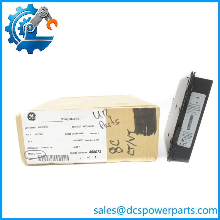
UR8CH
Application Scenarios & Field Pitfalls — The Engineer’s Perspective
Engineering Pain Point
CT-module failures can produce incorrect current measurements, protection alarms, or apparent relay-processing problems. Before replacing a GE Multilin , verify the CT secondary circuit, terminal connections, relay configuration, and associated CPU firmware. A replacement module should be evaluated as part of the complete UR relay rather than as an isolated circuit board.
Typical Applications
- Generator protection — Provides current measurement inputs for compatible UR generator-management applications.
- Feeder protection — Supplies phase and ground current signals to applicable feeder protection relays.
- Motor protection — Supports current measurement within compatible UR motor-management configurations.
- Transformer protection — Can provide CT measurements for UR transformer-protection applications where the relay configuration supports the module.
- Power distribution monitoring — Supplies current information used by the relay for protection, metering, and event analysis.
Technical Pitfalls
- Do not confuse with a digital I/O module.
Several online listings classify as an eight-channel digital I/O module, but the more specific technical references identify it as a CT/VT module. Its documented role is to provide phase and ground CT inputs to the Universal Relay. - Check the CT secondary rating.
The supports 1 A or 5 A CT secondary circuits. The installed protection scheme must be checked before connection; never assume that a 1 A and 5 A CT circuit can be treated interchangeably during field wiring. - Firmware generation matters.
Secondary technical documentation associates older hardware with older UR firmware generations and indicates compatibility considerations when newer CT/VT modules and CPUs are used. Verify the exact relay CPU and firmware before substitution rather than relying solely on the model number. - Do not treat it as a standalone relay.
provides the measurement interface; protection algorithms, logic, settings, communications, and overall relay operation reside in the associated Universal Relay hardware and software. - Verify the complete relay model.
A may be installed in different UR-family protection applications. Confirm the host relay model, chassis configuration, CPU version, CT wiring, and existing settings before approving a replacement. - CT circuits require proper field handling.
CT secondary circuits should never be casually opened while energized. Maintenance personnel should follow the site’s approved CT isolation and shorting procedure before disconnecting the module or its wiring.
Related Products
- GE Multilin UR8LV — Related CT/VT measurement module with a different hardware configuration.
- GE Multilin UR8FV — Another UR-family CT/VT module; verify exact measurement configuration before substitution.
- GE Multilin UR7CH — Related UR-family I/O hardware; not a direct CT/VT replacement.
- GE Multilin UR7EH — Related UR-series interface/I/O module.
- GE Multilin UR5EH — Transducer I/O module for compatible Universal Relay configurations.
- GE Multilin UR-RHV — UR-series high-voltage-range power supply module.
- GE Multilin C60 — Universal Relay family circuit-breaker protection application.
- GE Multilin 489 — Generator management relay within the UR platform family.
- GE Multilin 369 — Motor management relay within the UR family.
- GE Multilin 745 — Transformer management relay within the UR platform.
Procurement Note
For a replacement request, specify GE Multilin / UR-8CH and provide the complete host relay model, CPU hardware revision, firmware version, and CT secondary configuration whenever available.
For used or refurbished inventory, inspect the CT/VT connector area, terminal interfaces, board condition, module housing, and identification label. A visual inspection is not enough for a protection-system spare. Where practical, acceptance testing should verify CT input continuity, correct 1 A/5 A input configuration, relay recognition, measurement accuracy, and interaction with the installed protection application.
Identification warning: I would use “CT/VT Module” rather than “Digital I/O Module” or “8-channel input module” in the product title and catalog data. The former is supported by the more specific technical references, while the latter descriptions appear to be generic or incorrect classifications.