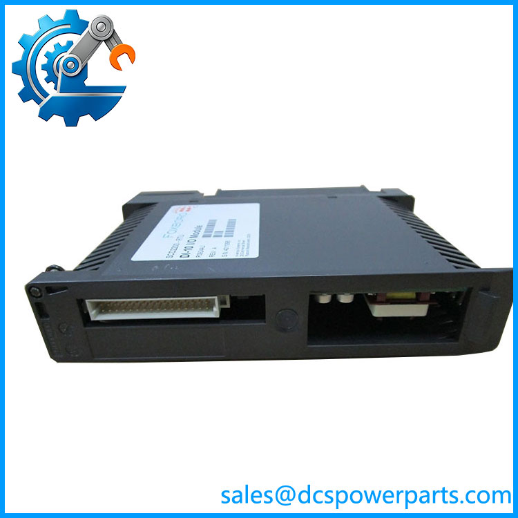
Description
FOXBORO P0924AU
Product Overview
The Foxboro P0924AU is the DI-10 digital input module used in the Foxboro SCD2200 Remote Terminal Unit platform. Its job is straightforward but important: acquire discrete field conditions and make those states available to the RTU control and SCADA layer. The module provides 16 digital input channels and is designed for mixed industrial signal environments where both DC contacts and higher-voltage AC status signals may be encountered. Foxboro documentation specifies support for 6–130 VDC and 20–260 VAC input ranges, making the P0924AU considerably different from low-voltage 12/24 VDC-only digital input modules.
Within an SCD2200 installation, the Foxboro P0924AU sits at the field-I/O level rather than acting as the RTU processor or communications controller. The SCD2200 architecture uses dedicated processor, communications, power-supply, and I/O modules, allowing a particular RTU configuration to be assembled around its field requirements. The P0924AU therefore works with the SCD2200 backplane and the RTU processing hardware rather than operating as a standalone PLC CPU. The manufacturer describes SCD2200 I/O modules as address-free modules with optical isolation and front diagnostic indication.
For legacy SCADA installations, the practical value of the Foxboro P0924AU is compatibility with existing field wiring and SCD2200 hardware. A replacement is not simply a matter of matching the number of channels. Input voltage class, termination arrangement, backplane type, module revision, and the existing RTU configuration all matter. This is particularly relevant when maintaining remote oil and gas, pipeline, water, utility, or other distributed monitoring installations where replacing the entire RTU is considerably more disruptive than restoring a failed I/O position. The was specifically developed for remote SCADA applications and supports modular expansion through its backplane architecture.
Product Introduction
A failed discrete-input channel can be deceptively disruptive: the field device may still operate correctly while the SCADA system simply stops seeing its status. The addresses this layer of the architecture with 16 optically isolated digital inputs and broad AC/DC input capability.
For a system upgrade or legacy replacement, check the complete module identification rather than buying on the number alone. The documented hardware version is 4.3.A, and the specified module operating range is -40°C to +85°C.
Key Technical Specifications
| Parameter | Specification |
|---|---|
| Product Model | |
| Manufacturer / Brand | Foxboro / Schneider Electric |
| Product Series | RTU |
| Module Designation | DI-10 |
| Product Type | Digital Input Module |
| Number of Digital Inputs | 16 |
| DC Input Range | +6 to +130 VDC |
| AC Input Range | 20 to 260 VAC |
| Input Isolation | Optical isolation |
| Isolation Rating | 3 kV |
| Counter Function | Digital input/counter functionality documented for DI-10 |
| Counter Resolution | 16-bit |
| Input Threshold Compatibility | IEC 61131-2 Type 1 and Type 3 |
| Operating Temperature | -40°C to +85°C |
| Relative Humidity | 5–95% non-condensing at 40°C |
| Altitude | 0–2,000 m |
| Mounting | Modular backplane |
| Approx. Module Weight | 284 g |
| Approx. Dimensions | 174 × 35 × 156 mm |
| Hardware Version Listed in Documentation | 4.3.A |
The manufacturer documentation specifies DI-10 as a 16-channel digital input/counter module with optically isolated inputs. It supports 24 VDC contacts as well as AC and DC inputs over the stated ranges; the documentation also identifies 16-bit counter resolution and input-threshold compatibility with IEC 61131-2 Type 1 and Type 3.
Major Features / Practical Advantages
1. Wide AC/DC Input Capability
The main engineering characteristic of the is its input range. The documented specification identifies +6 to +130 VDC and 20 to 260 VAC capability. That makes this module suitable for discrete status acquisition from a wider range of field circuits than a conventional 24 VDC-only DI card.
That flexibility is useful in legacy installations where field voltages are not perfectly standardized across every device. Before energizing a replacement, however, measure the actual field circuit. Do not assume that a historical drawing’s nominal voltage represents the voltage currently present at the cabinet terminals.
2. Sixteen Discrete Input Channels
Sixteen inputs provide a practical concentration of field-status points within a single I/O position. Typical signals can include switch status, equipment running indication, valve limit feedback, relay contacts, alarm contacts, and other binary process states.
The important point is that this is input acquisition, not output control. A cannot replace a P0924AV, P0924AW, or P0924AX simply because all of them belong to the same I/O family.
3. Optical Isolation
DI-10 documentation specifies optically isolated inputs and a 3 kV isolation rating. This separation is important when field wiring is exposed to voltage differences and electrical disturbances that should not be directly coupled into the RTU logic electronics.
Isolation does not eliminate the need for correct grounding, shielding, surge protection, or field termination practices. Those remain system-level engineering responsibilities.
4. Counter Capability
The DI-10 is documented as a digital input/counter module with 16-bit counter resolution. The counter capability can be useful when discrete pulses need to be accumulated or monitored rather than treated solely as static ON/OFF states.
For an existing installation, verify how the original RTU application configured these channels. A physical replacement does not automatically reproduce the intended logic configuration.
5. Wide Environmental Operating Range
The documentation specifies -40°C to +85°C operation for the DI-10 module. Relative humidity is specified at 5–95% non-condensing at 40°C, with an operating altitude range of 0–2,000 m.
This environmental range fits the remote-station orientation of the platform. Cabinet temperature, condensation control, vibration, and field wiring conditions still need to be evaluated at the installation site.
6. Designed for the Backplane Architecture
The is not a universal plug-in PLC card. It is part of the modular RTU architecture and mounts onto the system backplane. configurations can use 4-, 6-, or 12-slot backplanes, with larger configurations capable of linking multiple backplanes.
That distinction matters during procurement. A module that appears physically similar to an card is not necessarily electrically or logically interchangeable.
7. Legacy Replacement Value
is now primarily a legacy-system maintenance component. Schneider Electric’s documentation identifies the module and its hardware version, but procurement teams should not assume that a current-looking photograph represents the exact hardware revision required by an older RTU.
For a shutdown-critical installation, record the existing module’s complete nameplate information, hardware revision, serial number, termination arrangement, and surrounding configuration before placing the order.
Related Products
- P0924AS — AI-10-1 module with 8 analog inputs; intended for analog process measurements rather than discrete status signals.
- P0924UM — AI-10-V voltage-mode analog input module; used where bipolar voltage measurement is required.
- P0924CV — AO-3 analog output module with four analog output channels and 12-bit DAC resolution.
- P0924AV — DO-1 digital output module with eight relay output channels. It performs the opposite field-interface function from the .
- P0924AW — DO-2 module providing 16 relay output channels. It should not be treated as a substitute for the 16-input .
- P0924AX — DO-6 open-drain digital output/relay-driver module with 16 outputs.
- P0924CJ — DI-5, also a 16-channel digital input module, but intended for 12–24 VDC applications and incorporating four counter channels. Its electrical application is therefore different from the .
- P0924AY — IO-3 combination module incorporating analog and digital inputs plus analog and relay outputs. It is a mixed-I/O solution rather than a direct functional equivalent.
- P0924XW — IO-5 combination analog/digital I/O module with mixed input and output functions.
- R22 — CP-3 processor module. This is the RTU processing element and should not be confused with the field I/O module.
FAQ
What is the Foxboro used for?
It is a 16-channel DI-10 digital input module for the Foxboro RTU. Its primary purpose is acquiring discrete field signals for remote SCADA and control applications.
What input voltage does the support?
The product specification identifies +6 to +130 VDC and 20 to 260 VAC for the /DI-10. Older documentation also describes the module as supporting 24 VDC contacts and AC inputs.
Is a processor module?
No. This is an important distinction. is an I/O module, specifically DI-10. The processor is identified separately as the R22/CP-3 module.
Can I hot-swap this module?
Do not treat the as an unrestricted hot-swappable module. The documentation specifically describes plug-in/plug-out capability for the power-supply modules with the input power to that module disconnected; that does not establish unrestricted live removal of the I/O card.
For a live plant, follow the approved maintenance procedure and determine whether the associated I/O point can be safely bypassed or taken out of service.
Does support firmware v3.1?
There is no basis to assign a “firmware v3.1” to the from the model number. The documentation identifies hardware version 4.3.A for . Hardware revision and RTU/application software version should not be treated as interchangeable identifiers.
Can P0924CJ replace ?
Not as a direct electrical substitution. Both are 16-channel digital input modules, but P0924CJ is specified for 12–24 VDC inputs, while supports the substantially wider 6–130 VDC / 20–260 VAC range. The field voltage and existing configuration must therefore be checked before considering any substitution.
Will replacing the module preserve my RTU logic?
The is an I/O hardware module rather than the primary RTU processor. The application logic resides in the control architecture, but replacement still requires verification of the channel mapping, field termination, signal polarity, counter configuration, and RTU database. Do not assume that a physically compatible replacement automatically confirms correct application configuration.
How should a New Surplus be verified?
For a shutdown-critical spare, request clear photographs of the actual module nameplate and board identification. Confirm , DI-10 identification, hardware revision, connector/termination condition, and physical PCB revision where visible. If the supplier cannot document the exact item, treat “” in a listing title alone as insufficient evidence of compatibility.
Procurement Note
is a legacy DI-10 module, so procurement accuracy matters more than simply matching “16-channel digital input.” The manufacturer’s documentation confirms the model, 16-channel architecture, AC/DC input ranges, optical isolation, environmental range, and hardware revision.
Before purchasing a replacement, compare the installed module against the quotation at the part-number and hardware-revision level. Confirm the backplane, field termination arrangement, input voltage for every affected circuit, and the required RTU configuration. For New Surplus or previously installed stock, request actual nameplate photographs and inspection/test evidence rather than relying solely on catalog descriptions.
For a production-critical spare, keeping one verified with traceable identification is generally more useful than stocking a superficially similar I/O card that has a different electrical interface.