Description
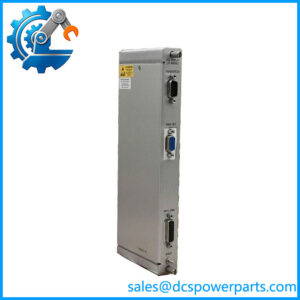
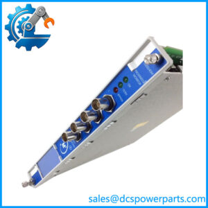
Bently Nevada 3500/42M 140734-99 Proximitor/Seismic Monitor
Key Technical Specifications
| Parameter | Specification |
|---|---|
| Manufacturer | Bently Nevada |
| Model | 3500/42M |
| Part Number | 140734-99 |
| Product Type | Proximitor/Seismic Monitor |
| Number of Channels | 4 |
| Channel Configuration | Pairs: 1–2 and 3–4 |
| Input Types | Proximity / seismic transducers |
| Measurement Functions | Vibration and position measurements |
| Configuration | 3500 Rack Configuration Software |
| Alarm Function | User-programmable alarm setpoints |
| System | Bently Nevada 3500 Monitoring System |
| Installation Position | 3500 rack slots 2–15 |
| Standard | API 670-oriented machinery protection architecture |
The 3500/42M is a four-channel monitor. Each channel pair can be programmed for a measurement function, allowing channels 1–2 and 3–4 to perform the same or different supported functions. The monitor continuously compares configured machine parameters with user-programmed alarm setpoints.
The monitor is an enhanced version of the original 3500/42 Proximitor/Seismic Monitor and is intended for the same general applications. Configuration and verification are performed through the 3500 Rack Configuration Software and associated test utilities.
Product Introduction
The Bently Nevada 3500/42M 140734-99 is a four-channel Proximitor/Seismic Monitor used within the 3500 Machinery Monitoring System. It receives signals from compatible proximity and seismic transducers, conditions those signals, calculates configured vibration or position parameters, and compares the resulting values with programmed alarm limits. This makes it a core measurement and protection component for rotating machinery such as turbines, compressors, pumps, and other critical machines.
For plant maintenance teams, the 3500/42M 140734-99 is more than a signal-processing card. Its configuration determines what each channel measures and which alarm parameters are active. A replacement therefore needs to be evaluated against the existing rack configuration, transducer type, channel assignment, alarm settings, and I/O module arrangement rather than judged only by physical fit.
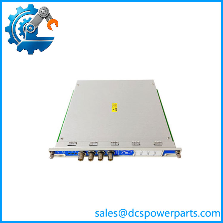
140734-01
Application Scenarios & Field Pitfalls — The Engineer’s Perspective
Engineering Pain Point
A vibration monitor can appear healthy while the actual measurement configuration is wrong. After replacing a 3500/42M, an incorrect transducer type, scale factor, zero position, channel function, or alarm configuration can produce plausible-looking values without providing the intended machinery protection.
Typical Applications
- Steam and Gas Turbines: Monitoring shaft vibration, axial position, eccentricity, and other critical turbine parameters.
- Centrifugal Compressors: Monitoring radial vibration and position-related parameters on compressor trains.
- Large Pumps and Motors: Monitoring bearing and shaft vibration using appropriate proximity or seismic transducers.
- Rotating Machinery Protection: Continuous comparison of measured parameters against configured alert and danger limits.
- Condition Monitoring: Providing machine measurements to the wider 3500 monitoring and plant maintenance architecture.
Technical Pitfalls
- Verify the complete part number. The requested 140734-99 should not be confused with other 3500/42M part-number variants. The 3500/42M family contains different hardware/configuration options.
- Check channel programming. The four channels are configured in pairs. Channels 1–2 may perform one function while channels 3–4 perform another.
- Match the transducer type. Proximity and seismic sensors have different signal characteristics and measurement applications. The replacement configuration must correspond to the installed field sensors.
- Preserve the existing configuration. Before replacement, upload or record the 3500 rack configuration whenever the original module remains accessible. This includes channel functions, scale factors, zero adjustments, alarm setpoints, and other configured parameters.
- Check the associated I/O module. The monitor and its field-side I/O hardware work as a system. Do not replace the monitor while assuming that any 3500-series I/O module is interchangeable.
- Do not remove the module casually from an operating rack. Bently Nevada documentation specifically warns that machinery protection is lost when the module is removed from the rack.
- Verify alarm behavior after replacement. A successful module startup does not prove correct protection operation. Check OK status, measured values, alert/danger setpoints, relay behavior, and the associated protection logic.
- Perform channel verification. Use the applicable 3500 test and configuration utilities to verify each channel rather than relying solely on front-panel status LEDs.
Related Products
- Bently Nevada 3500/40M — Proximitor Monitor for proximity-transducer applications; the 3500/42M adds seismic monitoring capability.
- Bently Nevada 3500/45 — Position Monitor for applications such as differential expansion and axial position; not a direct functional replacement.
- Bently Nevada 3500/22M — Transient Data Interface and rack interface module used for communication between the 3500 rack and host software.
- Bently Nevada 3500/32M — 4-channel relay module used for alarm and protection-system outputs.
- Bently Nevada 3500/33 — 16-channel relay module for broader alarm/control output requirements.
- Bently Nevada 3500/93 — System Display for local visualization of 3500 rack data and event information.
- Bently Nevada 3500/15 — Power supply module for the 3500 rack.
- Bently Nevada 3500/50 — Tachometer/Speed module for speed and related rotational measurements.
- Bently Nevada 3500/54 — Overspeed detection module for dedicated overspeed protection applications.
Procurement Note
For a 3500/42M 140734-99 replacement, capture the complete module part number, rack type, firmware/configuration information, associated I/O module part number, transducer model, channel assignments, and existing alarm settings before procurement.
A used or surplus module should be evaluated beyond visual condition. At minimum, inspect the front connector, PCB condition, indicators, and configuration identity, then perform channel verification with the correct test equipment before returning the machinery protection system to service. The 3500/42M manual also emphasizes ESD precautions when handling the module.