Description
Product Overview
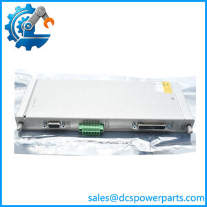
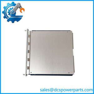
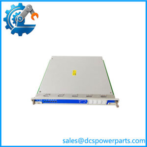
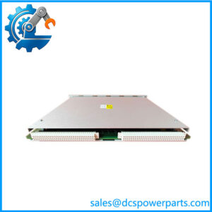
135489-02 is not a monitor and not a general-purpose I/O card; it is the intrinsically safe I/O module that lets a 3500 rack accept transducers sitting in a hazardous area without putting barrier hardware in the field. The barrier circuitry is built into the module, the terminations are built into the module, and the field wiring lands on it directly. Bently’s own datasheet is unambiguous about the configuration: this part carries two Proximitor/accelerometer channels and two Velomitor channels out of its four, and fits the 3500/42M Proximitor/Seismic monitor and the 3500/70M Recip Impulse/Velocity monitor.
That channel split is the single most important fact about the part number, and it is where sourcing goes wrong. The four barrier I/O modules for this monitor family look alike and sit in the same rack slot, but they are not interchangeable: 135489-01 is four Proximitor/accelerometer channels covering the 3500/42, /70 and /72; 135489-02 is the two-plus-two mix; 135489-03 is four Velomitor channels. A slot that expects four proximity probes and receives a two-plus-two module will not simply run degraded — two of its channels have no Proximitor conditioning at all. Buying by the shape of the module rather than the channel mix stamped on it is how a compressor train ends up with half its radial vibration channels dark.
The second distinction is termination style, because “internal” is not a preference here, it is the design. Barrier builds place the safety barrier between the field terminals and the monitor electronics, and the IS wiring practice that goes with that assumes the field cable terminates at the module. Bently supplies these barrier builds with internal terminations, and they are not offered with external termination boards; a rack wired for the external-termination arrangement (the standard, non-barrier modules such as 128240-01) is a different electrical layout, not a different option of the same module.
The third constraint is transducer compatibility, and it is more restrictive than most buyers expect. The internal-barrier system does not support 11 mm, 14 mm, 16 mm, 25 mm, 35 mm or 50 mm Proximitor sensors, nor velocity Seismoprobe sensors, nor the velocity-to-displacement converter on the 3500/40, nor magnetic pickups on the 3500/50, nor four-wire RTDs and thermocouples on the 3500/60 and /61, nor 1–5 V dc process variables on the 3500/62. On a hazardous-area machine that means the probe system must be one of the IS-rated types the datasheet lists as compatible — not whatever 3300-series probe happens to be in the storeroom. A plant that fits 135489-02 and then connects its existing 11 mm probes has bought a correct module for an incompatible sensor, and the loop will not work.
What the barrier buys is honest and narrower than marketing usually claims. It removes external barrier hardware from the marshalling cabinet and, in Bently’s words, does not degrade system performance the way external barriers can; it keeps standard and barrier monitors in the same rack, so a plant can convert one monitor at a time by replacing its I/O module rather than rebuilding the rack; and because each component is certified individually and as a system, the compatibility between the transducer, the barrier and the monitor does not have to be assembled from separate certificates. What it does require is an IS earthing module in every rack that contains internal barriers — the 3500/04-01, spare 136719-01 — and a channel-by-channel IS loop calculation, because the module publishes its own Uo, Io, Co and Lo values and the field cable’s capacitance and inductance have to fit inside them.
Technical Specifications
| Parameter | Value |
|---|---|
| Model | 135489-02 |
| Manufacturer | Bently Nevada — 3500 Machinery Protection System |
| Product type | I/O module with internal barriers and internal terminations |
| Compatible monitors | 3500/42M Proximitor/Seismic; 3500/70M Recip Impulse/Velocity (3500/42 and /70 in the datasheet’s naming) |
| Channel configuration | 2 Proximitor/accelerometer channels + 2 Velomitor channels |
| Barrier | Internal, integral to the 3500 system; no external barrier hardware |
| Terminations | Internal — field wiring lands on the module’s barrier terminal block |
| Proximity/acceleration bandwidth | 30 kHz |
| Amplitude accuracy (prox/accel) | 3 % at 10 kHz; −15/+10 % at 30 kHz |
| Phase accuracy (prox/accel) | −11° at 10 kHz |
| Prox/accel channel IS parameters | Um 250 V; Uo 27.45 V; Io 113.24 mA; Co 0.086 µF; Lo 2.77 mH |
| Velomitor accuracy and circuit | ±1 % amplitude; Uo 26.25 V; Rmin 297 Ω; Io 88.39 mA |
| Velomitor channel IS parameters | Um 250 V; Uo 26.25 V; Io 88.39 mA; Co 0.097 µF; Lo 4.55 mH |
| Physical | 241.3 × 24.4 × 163.1 mm (9.50 × 0.96 × 6.42 in); 0.46 kg (1.01 lb) |
| Rack requirement | One IS earthing module per rack containing internal barriers — 3500/04-01, spare 136719-01 |
| Agency approval | Selected by the 3500/04 order options: none, North American HazLoc, or Multi (CSA, ATEX, IECEx) |
| Transducers not supported | 11/14/16/25/35/50 mm Proximitor sensors; velocity Seismoprobe; velocity-to-displacement converter (/40); magnetic pickup (/50); 4-wire RTDs and thermocouples (/60, /61); 1–5 V dc process variables (/62) |
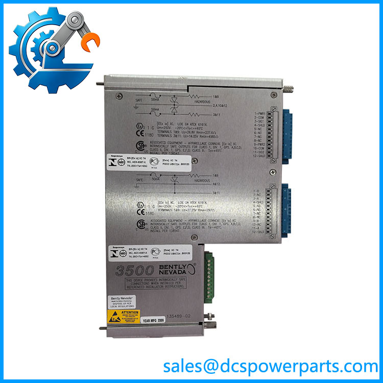
bently 135489-02
Key Features and Advantages
Barrier inside the module, not in the marshalling cabinet: the intrinsically safe interface travels with the I/O module, so the field wiring terminates at the rack and the external barrier enclosure, its cross-wiring and its separate certification disappear from the design.
Four channels in one slot: the barrier build keeps the 3500’s channel density, so a hazardous-area machine gets the same channel count per rack width as a safe-area one — 24.4 mm of rack for four transducer channels.
Two conditioning types on one module: two Proximitor/accelerometer channels and two Velomitor channels in the same assembly match the way a real machine is instrumented — radial displacement on two bearings and casing velocity on two, without a second module type in the spares list.
Bandwidth for real machinery diagnostics: 30 kHz on the prox/accel channels, with 3 % amplitude accuracy at 10 kHz and −15/+10 % at 30 kHz, is enough headroom for impact and rub events that a 1 kHz monitoring path would miss entirely.
Velomitor accuracy stated plainly: ±1 % amplitude on the velocity channels, with a 297 Ω minimum circuit resistance and 88.39 mA output current published for loop design rather than hidden behind a generic “compatible sensor” claim.
Conversion without a rack rebuild: standard and barrier monitors coexist in the same 3500 rack, so an existing installation can be upgraded one monitor at a time by swapping the I/O module — the migration path most brownfield plants actually need.
Certification that matches as a system: components are certified individually and as a system, so the transducer, barrier and monitor combination does not require the plant to reconcile three separate certificates to prove the loop is safe.
Published IS parameters for loop design: Uo, Io, Co and Lo are given per channel type, which is the data a hazardous-area loop calculation needs and the reason a barrier module can be verified rather than assumed.
Applications
Refinery and petrochemical compressor trains: radial vibration and casing velocity on machines whose transducers sit in a classified area while the 3500 rack sits in a safe or Div 2 room.
Reciprocating compressors and reciprocating engines: the 3500/70M pairing with 135489-02 puts two Proximitor channels on rod position or impulse and two Velomitor channels on frame or cylinder velocity, exactly the mix recip monitoring calls for.
LNG and gas processing plants: cryogenic and gas-handling machines where the transducer cable runs are long, the area classification is strict, and the loop capacitance and inductance budget in the barrier datasheet decides the cable type.
Offshore platforms and FPSOs: minimum footprint and no external barrier cabinets, with the IS earthing module as the only rack-level addition.
Ammonia, urea and methanol synthesis trains: CO₂ and synthesis-gas compressors where the probe systems are already IS-rated and the rack is being extended rather than replaced.
Brownfield upgrades: existing 3500 racks where a monitor is being converted to internal barriers without changing the rack, the cabling or the probe types already installed.
Related Products
135489-01 — four Proximitor/accelerometer channels with internal barriers and internal terminations, for the 3500/42, /70 and /72; the same slot, a different channel mix, and not interchangeable with 135489-02. 135489-03 — four Velomitor channels with internal barriers and internal terminations, for machines where all velocity channels are used and no proximity channel is needed. 135489-04 — the barrier I/O module for the 3500/40 Proximitor monitor, a different monitor family in the same 3500/04 barrier system. 135473-01 — barrier I/O module for the 3500/25 Keyphasor monitor, completing the phase-reference channel of an IS rack. 136703-01 — barrier I/O module for the 3500/50 Tachometer monitor. 136711-01 / 136711-02 / 137110-01 — barrier I/O modules for the 3500/60, 3500/61 and 3500/62 monitors, covering temperature and process variables in the same barrier system. 136719-01 — the IS earthing I/O module that must be installed in every rack containing internal barriers; 138257-01 is its front panel. 3500/04-01 — the ordering designation for the earthing module, with approval options for North American Hazloc or Multi (CSA, ATEX, IECEx). 128240-01 — the standard, non-barrier 3500/42M I/O module with external terminations; the arrangement 135489-02 is not a variant of. 3500/42M — the Proximitor/Seismic monitor this module serves; the monitoring electronics stay the same, the I/O module is what changes when the area classification does.
Installation and Maintenance
Before installation: confirm the channel mix. 135489-02 is two Proximitor/accelerometer channels and two Velomitor channels; 135489-01 is four prox/accel and 135489-03 is four Velomitor, and the rack will not silently compensate if the wrong one arrives. Confirm the probe systems against the datasheet’s compatible list — the barrier system excludes 11, 14, 16, 25, 35 and 50 mm Proximitor sensors, velocity Seismoprobes and the 4-wire temperature inputs — and confirm that the rack contains an IS earthing module, since a barrier rack without one is an incomplete installation rather than a variant. Verify the agency approval option against the area classification the plant actually has.
Installation: fit the module into its rack slot and land the field wiring on the module’s own barrier terminal block, observing the IS wiring practice for the loop — the barrier sits between those terminals and the monitor, so the cable length, capacitance and inductance are part of the safety calculation and not merely a signal-quality question. Check the loop against the published channel parameters: Uo 27.45 V, Io 113.24 mA, Co 0.086 µF and Lo 2.77 mH for the prox/accel channels, and Uo 26.25 V, Io 88.39 mA, Co 0.097 µF and Lo 4.55 mH for the Velomitor channels. Keep the earthing module and its front panel in place and record the approval marking on the rack.
Maintenance: when a channel goes dead, establish first whether the transducer is on the compatible list — a correctly installed barrier module connected to an excluded probe type produces exactly the symptoms of a failed module, and swapping modules will not fix it. Verify the earthing module before condemning an I/O module: a barrier rack with its earth path compromised shows up as unstable or noisy channels rather than as a clean failure. Keep the channel-mix record per slot, because the four barrier modules for this family are visually similar and the wrong spare fitted in a maintenance window is discovered as a monitoring gap. When converting a monitor from standard to barrier I/O, change the I/O module and confirm the monitor’s configuration still matches the transducer types now permitted.
Warranty and Quality
Every 135489-02 is supplied as the Bently Nevada 3500/04 internal-barrier I/O module defined by Bently’s 3500 Internal Barriers datasheet, ordering code 135489-02, not as the relay module, the external-termination module or the generic four-channel conditioner that resale listings describe. Documented for this part: four channels configured as two Proximitor/accelerometer plus two Velomitor, with internal barriers and internal terminations, for the 3500/42M Proximitor/Seismic and 3500/70M Recip Impulse/Velocity monitors; 30 kHz bandwidth on the prox/accel channels with 3 % amplitude accuracy at 10 kHz and −15/+10 % at 30 kHz, and −11° phase accuracy at 10 kHz; channel IS parameters of Um 250 V, Uo 27.45 V, Io 113.24 mA, Co 0.086 µF and Lo 2.77 mH for prox/accel, and Um 250 V, Uo 26.25 V, Io 88.39 mA, Co 0.097 µF and Lo 4.55 mH for Velomitor, with ±1 % amplitude accuracy and a 297 Ω minimum circuit resistance on the Velomitor path; dimensions of 241.3 × 24.4 × 163.1 mm at 0.46 kg; the requirement of an IS earthing module in every rack containing internal barriers, ordered as 3500/04-01 or supplied as spare 136719-01 with front panel 138257-01; compatibility with standard monitors in the same rack and the ability to convert by replacing I/O modules; and agency approval selected among none, North American HazLoc, or Multi (CSA, ATEX, IECEx). Units are inspected for terminal-block and connector condition, barrier circuit integrity, signs of heat or moisture, and for the part number against the channel mix. Six corrections are stated plainly: this part has internal barriers and internal terminations, not external terminations; it is an I/O module and not a relay module; it is not interchangeable with 135489-01 or 135489-03, whose channel mixes differ; it is not usable with 11, 14, 16, 25, 35 or 50 mm Proximitor sensors, velocity Seismoprobes, magnetic pickups, 4-wire RTDs and thermocouples, or 1–5 V dc process variables; it does not remove the need for an IS earthing module in the rack; and the module is part of a certified system, so the transducer must be from the compatible list rather than any handy probe. Module power consumption and the operating temperature range are not published in the datasheet text used here and are therefore not quoted rather than estimated. A 12-month repair, replacement or refund commitment applies. Technical support covers distinguishing 135489-02 from the other three barrier modules in this family before an order is placed, checking a proposed probe system against the barrier compatibility list, preparing the IS loop calculation from the published channel parameters, confirming the earthing module requirement and approval option, and diagnosing a dead channel where the module is healthy but the transducer is the wrong type.