Description
Product Overview
CPCI-10-D2 is not a card and not a controller. It is the chassis — the ten-slot CompactPCI card rack in which a duplex Vanguard controller is assembled — and reading it as a module is the first mistake the resale channel makes. CCC’s own data sheet for the CPCI-10-D2-NPS variant describes it as a duplex ten-slot Vac and HVdc chassis, which means the model number compresses four facts: CompactPCI as the bus standard, ten slots, duplex as the configuration, and a second-generation design. The -NPS suffix adds the AC and HVdc input capability, which is why the same family appears in the channel as “10SL, Duplex w/Fan, AC&HVDC”.
The architecture inside the chassis is the part that matters when a plant is specifying one. Cards mount at the front in positions numbered one to ten, right to left, and transition modules mount at the back, numbered one to ten left to right, with each module required to sit opposite its own card. A duplex system takes two MPU processor cards — MPU A in slot 1 and MPU B in slot 10 — up to three pairs of IOC-555 I/O cards, with the A cards in slots 3, 5 and 7 and their B counterparts in slots 4, 6 and 8, and an EVC card in slots 2 and 9 where one is required. The RCC cards are not permitted in this duplex configuration, and every unused slot must be closed with a blank panel, because an open slot in a card rack is an airflow and dust problem rather than a cosmetic one.
The reason the chassis is built this way, with wiring at the back and cards at the front, is availability. CCC’s documentation says the subrack at the back provides the cable connections that allow front-card replacement without disconnecting the cables in the back. In a compressor train, that means a processor or an I/O card can be changed while the machine runs, because the field and serial wiring stays on the transition modules — the TMPU behind the processor and the TIOCs behind the I/O cards. The chassis is therefore not a passive enclosure; it is the physical arrangement that makes hot-swap practical, and its two-sided access requirement is right there in the installation notes: front and rear access to the chassis is required for installing cards, transition modules, fans, power supplies and cables.
Power is handled as four supplies rather than one. The chassis takes four PSMU-350-3 modules, and CCC is explicit that a duplex chassis is always installed with four power supplies — redundancy is the design assumption, not an option. On the -NPS variant the input ranges are 90 to 264 Vac and 90 to 320 Vdc at 475 W, with four input connections on the back, a Type F fuse per supply rated 6.3 A at 200 V, a hold time of at least one AC cycle, and a power fault relay with normally-open and normally-closed contacts rated 1 A at 30 V. A note in the documentation is worth repeating because it explains a false alarm that technicians chase: a power fault may or may not be reported when a working supply is removed from a redundant group, or when input power is lost to one supply in a redundant group.
Two backplane details decide whether the chassis works at all. There is a jumper on the left side of the backplane that connects the 5 Vdc and VI/O terminals; it is installed at manufacturing, and it is required for MPU-to-IOC card communication. And the chassis provides colour-coded keying for each card and module type, so that a card cannot be fitted to a slot it does not belong in — CCC’s wording is that removing or changing the location of the coloured keys is prohibited. Both details are the kind that get “tidied up” during a refurbishment and then produce a system that will not communicate.
Cooling is a front-loading tray, and it is a maintenance item rather than an accessory. The FAN-10-2 assembly carries six 92 mm fans, 60 cfm each, on double-shielded ball bearings with a 60,000-hour MTBF rating, and slides in from the front on two locking screws. It can be removed and replaced while powered but must not be absent for more than a minute, because the cards’ temperature limits will be exceeded; CCC recommends quarterly inspection and replacement of the assembly every five years. The chassis itself needs at least one unit rack — 1.75 inch, 44.5 mm — of clear space above and below it in the panel layout, and more is recommended.
The placement question is a separate one from the specification question. This chassis is a Vanguard component: the cards that go in it are MPU-1002 and MPU-1004 with their TMPUs, IOC-555-D with its TIOCs, EVC cards where fitted, and PSMU-350-3 supplies. A plant buying CPCI-10-D2 as a bare chassis needs to know which generation of MPU card the backplane and keying were built for, and whether the unit in hand is the plain AC version or the -NPS AC-and-HVdc version, because the two take different input wiring.
Technical Specifications
| Parameter | Value |
|---|---|
| Model | CPCI-10-D2; AC and HVdc variant CPCI-10-D2-NPS |
| Manufacturer | Compressor Controls Corporation (CCC), Des Moines, Iowa, USA |
| Type | Duplex ten-slot CompactPCI card chassis |
| Bus standard | CompactPCI (PICMG 2.0 / 2.1) |
| Slot count | 10 front card slots plus 10 matching rear transition-module positions |
| Slot numbering | Cards 1–10 right to left at the front; transition modules 1–10 left to right at the rear |
| Position rule | Each transition module must match its front card’s slot |
| Processor slots | MPU A in slot 1, MPU B in slot 10 |
| I/O slots | Up to three IOC-555-D pairs: A in slots 3, 5, 7; B in slots 4, 6, 8 |
| Other slots | EVC A in slot 2, EVC B in slot 9 where required; RCC cards not allowed |
| Power supplies | Four PSMU-350-3 modules; a duplex chassis is always fitted with four |
| AC input (-NPS) | 90–264 Vac, 475 W |
| DC input (-NPS) | 90–320 Vdc, 475 W |
| Input connections | Four, on the rear of the chassis |
| Fusing | Type F, 6.3 A at 200 V per input (CCC part 20-401800-063) |
| Hold time | Minimum one AC cycle |
| Fault relay | Power fault relay, NO and NC contacts, 1 A at 30 V |
| Backplane jumper | 5 Vdc to VI/O link, factory-installed, required for MPU–IOC communication |
| Keying | Colour-coded card and module keys; relocation prohibited |
| Cooling | FAN-10-2 front-loading tray, six 92 mm fans, 60 cfm each, 60,000 h MTBF |
| Fan tray size | 419 × 38 × 261 mm; removable under power for no more than one minute |
| Chassis dimensions | 310 × 483 × 300 mm (12.22 × 19.00 × 12 in), 19-inch rack |
| Rack clearance | At least 1.75 in (44.5 mm) above and below the chassis |
| Mounting | Front-mount or recessed flange; front and rear access required |
| Approvals | CE; CSA pending (as stated in the data sheet) |
| Document reference | DS5109, revision 1.8, System Release 9.3, September 2013 |
| Platform | Up to 576 I/O points, up to 16 control applications, IEC 61131-3, 0 °C to +55 °C |
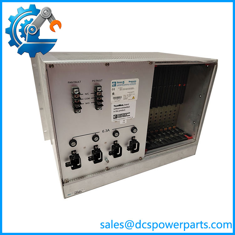
Vanguard-CPCI-10-D2
Key Features and Advantages
Wiring that stays in place: rear-mounted transition modules let a front card be replaced without disconnecting the plant cabling, which is what makes hot swap usable on a running machine.
A layout that is defined rather than discretionary: slots 1 and 10 for the processors, 3 through 8 for the I/O pairs, 2 and 9 for EVC, with a stated rule for each type and blank panels everywhere else.
Redundancy designed in: four PSMU-350-3 supplies in every duplex chassis, with a power fault relay to report a lost supply.
Keying that prevents the wrong card in the wrong slot: colour-coded keys are factory-set, and the documentation forbids moving them.
A documented backplane detail that decides communication: the factory-installed 5 Vdc to VI/O jumper is required for MPU–IOC communication and is easily lost in a refurbishment.
A real cooling design, maintained on a schedule: six-fan tray with a 60,000-hour bearing rating, quarterly inspection and five-year replacement.
CompactPCI on a 19-inch rack: a standard bus in a standard width, with the depth kept to 300 mm so it fits a conventional panel.
Front or recessed mounting: the flange can be mounted forward or at the back, so the chassis fits either cabinet style.
Applications
Compressor anti-surge control: the physical platform for the duplex controller that holds a centrifugal compressor away from surge.
Performance and quench control: the same chassis carrying the applications that keep the operating point inside the safe envelope.
Steam and gas turbine control: governor and limit functions on the same train, in the same card rack.
Duplex machine-train installations: hot-backup processor pairs, where the chassis and its four supplies are the availability argument.
Train-wide integration: configurations up to 576 I/O points and sixteen applications, served by one ten-slot chassis with three I/O pairs.
Legacy system support: plants maintaining a Vanguard system, where the chassis, its keying and its backplane jumper are the structural parts that keep the rest usable.
Retrofit and re-control: cabinets being renewed, where the existing chassis is retained and the cards around it are replaced.
Spares and exchanges: chassis-level spares held for a fleet, where the -NPS and plain versions and the card generation have to be recorded.
Related Products
CPCI-10-D2-NPS — the AC and HVdc input variant of this chassis, with four input connections on the rear; different input wiring from the plain version. CPCI-10-D — the earlier duplex chassis of the same family, referenced alongside the -D2 as a PSMU-350 host. MPU-1004 / MPU-1002 — the duplex processor card pair that occupies slots 1 and 10. TMPU-1004 / TMPU-1002 — the processor transition modules at the rear of the processor slots, carrying the chassis serial connections. IOC-555-D (17-550555-001) — the I/O card, up to three pairs in slots 3 to 8. TIOC-555HD — the transition module paired with each IOC card, where the FTA field terminations land. EVC cards — the cards permitted in slots 2 and 9 where the application requires them. PSMU-350-3 — the power supply module; four are fitted in a duplex chassis. FAN-10-2 — the front-loading fan tray, six fans, replaced on a five-year cycle.
Installation and Maintenance
Before installation: establish which version the chassis is — plain AC or the -NPS AC-and-HVdc variant — because the input wiring and rating differ, and establish which MPU generation the backplane and keying were built for. Check the rack clearance: at least one unit rack above and below, and more if the cabinet allows it. Confirm that front and rear access will be available after mounting, since both are needed to install and service the cards, modules, fans, supplies and cables. Inspect the backplane keys before anything is fitted, and confirm the 5 Vdc to VI/O jumper is present on the left side of the backplane.
Installation: mount the chassis on the 19-inch rack with the flange forward or recessed as the cabinet requires, and connect the safety ground at the chassis ground point between the input connectors. Connect the four power inputs and confirm the fuse type and rating at each; CCC specifies Type F at 6.3 A and 200 V. Fit the supplies, then the cards and their transition modules in matching positions, and close every unused slot with a blank panel. On power-up, check each supply for Input OK and no Fault indication, and check the power fault relay state against the plant’s wiring before the controller is started.
Maintenance: inspect the fan tray quarterly for free rotation, bearing play and dust, and plan replacement of the assembly on the five-year cycle; never leave the tray out for more than a minute with the system powered. Check the backplane keys and the 5 Vdc to VI/O jumper at every outage, because both are the kind of detail a rebuild loses. Verify the fault relay wiring and the input fuses when a supply is replaced, and remember that removing a healthy supply from a redundant group may or may not raise a power fault — clear the alarm rather than chasing a phantom. Keep the chassis interior free of dust, confirm the blank panels are in place, and log the chassis version, the card generation and the fitted supplies against the plant’s asset record so that the next spare is ordered correctly.
Warranty and Quality
Every is supplied as the CCC Series 5 Vanguard duplex ten-slot CompactPCI chassis — the card rack whose front slots 1 to 10 take the processor pair and up to three I/O pairs, whose rear positions take the matching transition modules under colour-coded keys, which houses four PSMU-350-3 power supplies, carries a factory-installed 5 Vdc to VI/O backplane jumper required for MPU–IOC communication, mounts on a 19-inch rack at 310 × 483 × 300 mm with at least 1.75 inch of clearance above and below, and cools through a front-loading FAN-10-2 tray of six 92 mm fans — in the AC version or the -NPS AC-and-HVdc version at 90–264 Vac or 90–320 Vdc, 475 W, with four rear input connections and a power fault relay. Units are offered as used, refurbished or surplus stock exactly as described, inspected for backplane connector damage and bent pins, key presence and colour coding, jumper presence at the 5 Vdc to VI/O position, subrack and card-guide condition, fan tray and connector integrity, fuse holders and input terminals, and signs of heat, arcing or contamination, with the chassis version, revision and card generation recorded against the article rather than assumed from the model number. Six corrections are stated plainly: this is a chassis and card rack, not a control and interface module, a signal-processing module, an industrial computing platform or a controller; the model number describes CompactPCI, ten slots, duplex configuration and a second-generation design, while the -NPS suffix adds AC and HVdc input rather than denoting a different slot count or a different bus; the plain and the -NPS version take different input wiring and must not be treated as interchangeable at the terminals; the four supplies are a design requirement of the duplex chassis and not optional loading; the RCC cards are not permitted in this configuration and the unused slots require blank panels; and the CE marking with CSA pending, the 1 A at 30 V relay rating and the 60,000-hour fan MTBF are the data sheet’s figures for the -NPS variant rather than specifications that carry over unqualified to every chassis of this family. A 12-month repair, replacement or refund commitment applies. Technical support covers version and revision identification, card-generation and backplane-keying questions, slot assignment for processors, I/O pairs and EVC cards, the 5 Vdc to VI/O jumper and its role in MPU–IOC communication, power supply loading and fault relay behaviour, fan tray maintenance intervals and replacement, and the spares, repair and re-control options for plants keeping Series 5 Vanguard systems in service.
免费
今天 11:15