Description
Product Overview
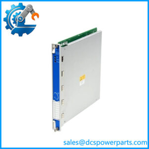
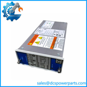
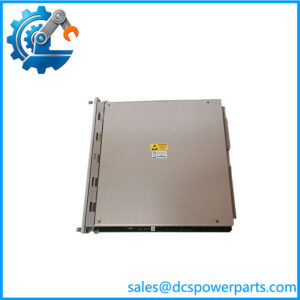
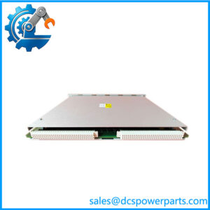
135031-01 is the modem variant of the 3500/20 rear I/O module, and the ordering information in Bently Nevada’s own 3500/20 data sheet settles its identity in one line: in the spares list it reads “RIM I/O Module with Modem Interface”, alongside 125768-01 “RIM I/O Module with RS232/RS422 Interface” and 125760-01 “Data Manager I/O Module”. In the ordering scheme, the rack interface module is ordered as 3500/20-AA-BB-CC, where the B field selects the I/O module type and option 01 is “I/O module with built-in modem”. A rack built as 3500/20-01-01-00 or -01 therefore carries exactly this module behind its standard RIM.
The RIM itself is the primary interface to a 3500 rack: it supports the proprietary protocol used to configure the rack and retrieve machinery data, and it must sit in slot 1 of the rack, next to the power supplies. Bently Nevada is explicit that the RIM is not part of the critical monitoring path and has no effect on the normal operation of the monitoring system — a point worth repeating, because it defines what a failure of this module does and does not mean. One RIM is required per rack, and in a TMR application the rack needs the TMR version of the RIM, which adds monitor channel comparison: it continually compares the outputs of three redundant monitors and flags a monitor whose information falls outside a configured percentage of the other two, placing an event in the System Event List.
The module’s job is the rear half of that interface. The RIM’s own front panel carries an RS232 configuration port at 38.4 k baud, intended for configuring or retrieving data from that rack alone. The rear I/O module is what extends the rack’s communications beyond the front panel: in the modem form it provides an internal Hayes AT-compatible modem at up to 14.4 k baud, over a cable of 2.1 metres to a phone jack, which is how a remote rack is reached over a dial-up line where no network exists. That is the whole function. It is a communications module, and the descriptions in the channel that turn it into a position monitor, an analog output driver or a discrete alarm relay interface describe hardware that does not exist in this slot.
The comparison with its siblings is the practical way to be sure which one is in hand. The RS232/RS422 module, 125768-01, is the direct-serial version: it supports RS232 to 30 metres and RS422 to 1200 metres, has a switch to select between the two, and supports an external modem through the RS232 port. The modem module, 135031-01, puts the modem inside the rack and adds the telephone interface, at the cost of a narrower environmental range and a much shorter cable run. The Data Manager I/O module, 125760-01, is different again, carrying two sets of ports at a fixed 9600 baud for the external communication processors. Three modules, three rear slots’ worth of different capability, and the part number is what distinguishes them.
The environment is where the modem form gives something away. The RIM and the RS232/RS422 I/O module are rated from −30 °C to +65 °C, but the modem I/O module is rated from 0 °C to +50 °C, with 95 % non-condensing humidity. A plant that specifies the modem module for an outdoor or unheated cabinet should notice that it has just narrowed the rack’s operating window, and the module’s shorter cable length — 2.1 metres to the phone jack rather than 30 metres of serial cable — is a cabling constraint that has to be designed in rather than discovered at commissioning.
Physical form follows the rack: the RIM main board occupies one full-height front slot and the I/O module one full-height rear slot, and the two are a set. The main board is 241.3 × 24.4 × 241.8 mm and 0.91 kg; the I/O module is the shorter 99.1 mm depth and 0.45 kg. The rear slot is where the field connections live, which is the same arrangement that lets a 3500 rack be serviced from the front without opening the marshalling side.
One further detail connects this module to the rack’s alarm behaviour without making it the alarm path. The RIM provides an I/O Module OK relay that indicates whether the rack is operating normally or has detected a fault, with the user able to select an open or closed contact to annunciate a NOT OK condition; the relay is always normally energised and is rated 5 A at 24 Vdc or 120 Vac, 120 W or 600 VA switched, with arc suppressors on the normally-closed contacts. That relay is part of the RIM’s function, not the modem’s, and a buyer who needs it should be clear that it comes from the main board.
Technical Specifications
| Parameter | Value |
|---|---|
| Model | 135031-01 |
| Description (OEM spares list) | RIM I/O Module with Modem Interface |
| System order code | 3500/20-01-01-CC (B option 01, “I/O module with built-in modem”) |
| Manufacturer | Bently Nevada, a Baker Hughes business |
| Platform | 3500 Machinery Protection System |
| Module type | Rear I/O module — communications |
| Paired main board | 3500/20 RIM, 125744-02 (standard) or 125744-01 (TMR) |
| Sibling modules | 125768-01 /RS422 I/O; 125760-01 Data Manager I/O |
| Modem | Internal, Hayes AT-compatible |
| Modem data rate | 14.4 k baud maximum |
| Modem cable length | 2.1 m (7 ft) to the phone jack |
| Serial capability of the family | 38.4 k baud maximum, auto-baud capable |
| Protocol | Bently Nevada proprietary |
| Rack address range | 63 addresses, set by the RIM’s address switch |
| Slot requirement | One full-height rear slot; RIM main board in front slot 1 |
| Dimensions | 241.3 × 24.4 × 99.1 mm (9.50 × 0.96 × 3.90 in) |
| Weight | 0.45 kg (1.0 lb) |
| Operating temperature (modem I/O) | 0 °C to +50 °C (+32 °F to +122 °F) |
| Storage temperature | −40 °C to +85 °C (−40 °F to +185 °F) |
| Humidity | 95 %, non-condensing |
| RIM operating temperature (for contrast) | −30 °C to +65 °C |
| RIM power consumption | 4.75 W typical |
| I/O Module OK relay (on RIM) | 5 A at 24 Vdc / 120 Vac; 120 W / 600 VA; normally energised |
| Data sheet | 141531 Rev. C |
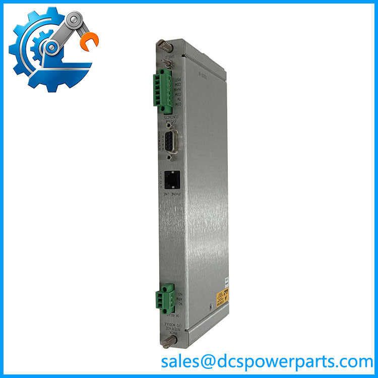
Bently 135031-01
Key Features and Advantages
Dial-up reach where there is no network: a modem inside the rack lets a remote 3500 be configured and interrogated over a telephone line.
A defined position in the ordering scheme: B option 01 in 3500/20-AA-BB-CC identifies this module exactly, so a rack’s original configuration can be read from its order code.
Separation from the monitoring path: the RIM and its I/O module are not in the critical monitoring path, so a communications fault does not compromise machinery protection.
One rack, one interface: the RIM is required once per rack and must sit in slot 1, which makes the pairing rule unambiguous.
A companion for the TMR case: the TMR RIM adds monitor channel comparison, so redundancy is a property of the main board rather than of this module.
Front-panel configuration kept separate: the RIM’s own configuration port serves that rack alone, independent of what the rear module provides.
A clear choice against the siblings: the modem form versus the /RS422 form versus the Data Manager form — three different capabilities, one part number each.
Physical economy: a 99.1 mm-depth rear module at 0.45 kg, so the rack’s front and rear arrangement is preserved.
Applications
Remote machinery protection racks: installations reached over a dial-up line, where the internal modem is the only communications route.
Compressor and turbine trains: the 3500 racks monitoring those machines, where the interface module carries configuration and data retrieval.
Unmanned or lightly staffed stations: sites where a telephone line is more reliable than a network, and the rack has to be interrogated from a central office.
Legacy communications estates: plants still using dial-up data collection, where the modem module is the part that keeps the practice working.
Rack configuration and data collection: reading and changing rack configuration, and retrieving machinery information, through the RIM interface.
Spares and exchanges: replacement of a failed rear module identified by 135031-01 rather than by a generic “RIM I/O module” description.
Migration decisions: sites deciding between the modem form and the / form, where the cable length and temperature range decide the choice.
TMR installations: racks where the TMR RIM provides monitor channel comparison and the rear module provides the communications route.
Related Products
125744-02 — Standard Rack Interface Module main board; the front-slot board this module sits behind. 125744-01 — TMR Rack Interface Module, which adds monitor channel comparison; the correct main board for a TMR rack. 125768-01 — RIM I/O Module with / Interface: the direct-serial alternative, with a 30 m / 1200 m reach and an / selector switch. 125760-01 — Data Manager I/O Module: two sets of ports at a fixed 9600 baud for external communication processors; a different function entirely. 3500/20 rack interface module, order code 3500/20-01-01-CC — the ordered assembly this module completes, with the standard RIM and modem I/O. 129768 — RIM Operation and Maintenance Manual, the reference for the module’s configuration and diagnostics. 02290860 — modem cable for the rack-to-external-modem path; the cabling the modem form does not need. 130118-AAAA-BB / 130120-AAAA-BB — Host-to-rack and cables, for the serial rather than the dial-up route. 128755-01 — Firmware IC, for PWA 125744-01 Rev P or later and PWA 125744-02 Rev N or later.
Installation and Maintenance
Before installation: confirm that the rack is meant to be a modem rack. The rear module’s part number, 135031-01, corresponds to B option 01; a rack ordered with option 02 takes the / module 125768-01 and the two are not interchangeable in function. Check the main board in front: the standard RIM 125744-02 or the TMR RIM 125744-01 depending on the application. Confirm the cabinet’s temperature range against the modem module’s 0 °C to +50 °C limit, and confirm a telephone line is available within 2.1 metres of the rack, because the module’s cable is short by design.
Installation: fit the module into the rear slot that corresponds to the RIM’s front slot 1 position, and seat it fully. Make the telephone connection and verify the line before configuration is attempted. Confirm the rack address set on the RIM’s address switch, since the module provides the route but the address identifies the rack, and verify the configuration keylock position — RUN locks out configuration changes, PROGRAM permits them. Then check the front-panel indications: the OK, TX/RX, TM and CONFIG OK LEDs describe the rack’s state, and the I/O Module OK relay reports the rack’s not-ok condition to the plant.
Maintenance: verify the modem path as part of the routine communications check rather than only after a failure, since a dial-up route that is never exercised cannot be shown to work. Inspect the rear connector and the telephone lead for damage, check the module is still seated after work in adjacent slots, and confirm the humidity and temperature inside the cabinet stay within the module’s narrower rating. When replacing a module, keep the main board in place unless it too is suspect — the pair is matched but the modules are separate parts, and the firmware IC reference applies to the main board rather than to the I/O module. Record the rack’s order code and both part numbers in the asset register so that the next spare is the right one.
Warranty and Quality
Every 135031-01 is supplied as the Bently Nevada 3500/20 RIM I/O Module with Modem Interface — the rear-slot communications module that carries a Hayes AT-compatible internal modem at up to 14.4 k baud over a 2.1 metre lead to a phone jack, paired with a 3500/20 Rack Interface Module main board in slot 1 of the rack, occupying one full-height rear slot at 241.3 × 24.4 × 99.1 mm and 0.45 kg, rated from 0 °C to +50 °C at 95 % non-condensing humidity, in a system where the RIM supports the proprietary configuration and data-retrieval protocol at 38.4 k baud, provides an I/O Module OK relay rated 5 A at 24 Vdc or 120 Vac with arc suppressors on the normally-closed contacts, carries 63 rack addresses and a RUN/PROGRAM configuration keylock, and remains outside the critical monitoring path by design. Units are offered as used, refurbished or surplus stock exactly as described, inspected for rear-connector pin damage, modem lead and jack condition, board contamination, component and capacitor condition, and signs of heat or moisture damage, and are identified by the part number against the rack’s order code rather than by a generic module description. Six corrections are stated plainly: 135031-01 is the modem I/O module for the 3500/20 Rack Interface Module and not a 3500/45 position monitor, an analog output module, a discrete alarm relay module or a monitor card of any kind; its function is communications — configuration and data retrieval — and it neither processes machinery signals nor participates in the protection path; the RIM main board and the rear I/O module are separate parts with separate part numbers, and a rack described as “135031-01” is only the rear half of the assembly; the / module 125768-01 and the Data Manager module 125760-01 are different articles, and the modem form should not be substituted for either on the strength of a shared “RIM I/O module” description; the modem module’s 0 °C to +50 °C range is narrower than the −30 °C to +65 °C rating of the RIM and the serial module, so the rack’s environmental rating changes when this module is fitted; and the 2.1 metre telephone lead is a cable-length limit rather than a recommendation. A 12-month repair, replacement or refund commitment applies. Technical support covers part-number and order-code identification, standard versus TMR main board pairing, modem versus / versus Data Manager module selection, rack address and keylock configuration, front-panel indication and I/O Module OK relay behaviour, and the spares, repair and communications-migration options for plants running 3500 racks on dial-up links.