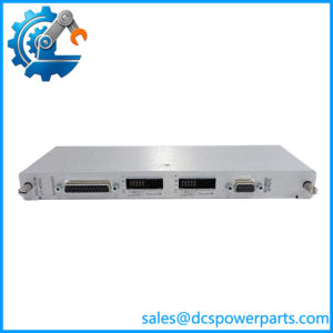
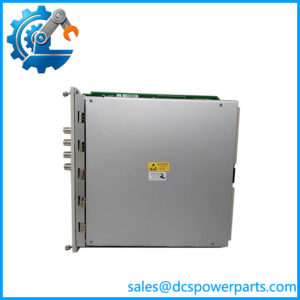
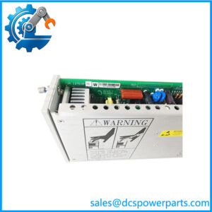
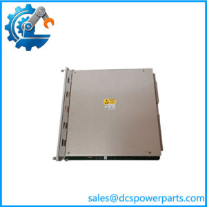
Description
Key Technical Specifications
| Parameter | Specification |
|---|---|
| Manufacturer | Bently Nevada |
| Series | 3500 |
| Module | 3500/50 Tachometer Module |
| Part Number | 133434-01 |
| Channels | 2 |
| Primary Function | Speed / Tachometer Monitoring |
| Supported Measurements | Speed, rotor acceleration, zero speed |
| Input Type | Speed sensor / proximity-type tachometer input |
| Alarm Functions | Configurable setpoints |
| Rack Interface | Bently Nevada 3500 rack |
| Recorder Outputs | Configurable proportional outputs |
| Relay Logic | Programmable through 3500 configuration |
| Typical Applications | Turbine, compressor, pump, generator and other rotating machinery |
| Monitoring System | 3500 Machinery Protection System |
Important: The exact electrical characteristics, input thresholds, transducer compatibility, and output configuration depend on the installed 3500/50 variant and associated I/O module. Verify the OEM datasheet and the complete 133434-01 ordering code before installation.
Product Introduction
Bently Nevada 3500/50 133434-01 Overview
The Bently Nevada 3500/50 133434-01 is a two-channel Tachometer Module used in the 3500 machinery monitoring platform. It processes speed-related signals from rotating equipment and can monitor shaft speed, rotor acceleration, and zero-speed conditions. The module is commonly used where rotational-speed information is required for machinery protection, control, or plant monitoring.
The important point is that this is a speed-monitoring module, not a general-purpose vibration input card. It is typically installed where accurate shaft-speed information is needed for turbine, compressor, pump, generator, or other rotating machinery applications. Existing transducer type and I/O configuration should be checked before substitution.
Application Scenarios & Field Pitfalls
Engineering Pain Point
A speed-monitoring module usually gets attention after the machine has already stopped behaving correctly. A turbine may report an incorrect speed, a compressor may fail to prove zero speed, or a control system may receive an unexpected tachometer value. At that point, replacing the module immediately is tempting. That is often the wrong first move. The sensor, target geometry, wiring, termination hardware, configuration, and module all have to be separated during troubleshooting.
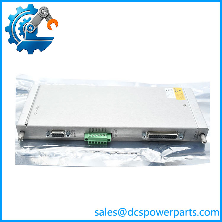
133434-01
Typical Applications
- Steam Turbine — Shaft speed monitoring and overspeed-related machinery protection.
- Gas Turbine — Rotor speed measurement during startup, shutdown, and normal operation.
- Compressor Train — Speed monitoring for rotating compressor machinery and associated protection logic.
- Power Generation — Generator or auxiliary rotating-equipment speed monitoring.
Technical Pitfalls to Avoid
- Do not blame the module before checking the speed probe.
A damaged proximity probe, incorrect probe gap, poor cable termination, or damaged extension cable can produce symptoms that look like a failed tachometer channel. - Check the actual signal at the input.
In our experience, measuring the field signal is more useful than repeatedly resetting the rack. Confirm that the sensor produces a valid signal throughout the expected speed range. - Verify the configured measurement and alarm parameters.
Speed monitoring is highly dependent on configuration. Incorrect pulses-per-revolution or alarm settings can result in a perfectly healthy module reporting an apparently incorrect machine speed.
Standard Operating Procedure (SOP) for Quality Control
A 3500/50 replacement should be treated as a machinery-protection component, not simply as a plug-in electronic spare.
1. Inbound Inspection
Before testing:
- Verify the Bently Nevada 3500/50 identification.
- Confirm the complete 133434-01 part number.
- Inspect the front panel, connector interface, board assembly, and housing.
- Check for oxidation, corrosion, contamination, cracked components, or mechanical damage.
- Inspect connector pins for bending or contamination.
- Record serial number and revision information where available.
2. Live Functional Testing
Where a suitable 3500 test rack and signal source are available:
- Install the module in the appropriate 3500 rack.
- Verify module initialization and rack communication.
- Apply a controlled tachometer/speed signal.
- Confirm channel response.
- Verify speed measurement behavior over an appropriate test range.
- Check alarm operation against the configured test setpoints.
- Verify relay/output behavior where applicable.
- Compare displayed speed against the calibrated test source.
A meaningful functional test should use a known signal source. Simply confirming that the module powers up is not enough.
3. Final Packaging
After QC:
- Place the module in anti-static protective packaging.
- Protect the connector and front-panel interface from impact.
- Attach the QC identification label.
- Record the test results and observed hardware revision.
- Package the module to prevent electrostatic and mechanical damage during storage and transportation.
The objective is traceable functional verification, not a claim of zero future failure.
Frequently Asked Questions
Q1: Can the Bently Nevada 3500/50 133434-01 replace another 3500/50 directly?
Not necessarily. The 3500/50 family contains different ordering configurations, including differences associated with I/O arrangements and installation requirements. Match the complete part number, transducer arrangement, rack configuration, and application before approving a replacement.
Q2: What does the 3500/50 actually monitor?
The 3500/50 is designed for tachometer-related measurements. Depending on configuration, it can monitor rotational speed, rotor acceleration, and zero-speed conditions. It is therefore commonly associated with rotating machinery protection and speed-related control functions.
Q3: Will replacing the 3500/50 erase my existing 3500 configuration?
The replacement module should not be treated as a substitute for the rack’s configuration-management process. Before removing a functioning module, document the existing configuration and verify the replacement against the site’s 3500 configuration records. Alarm setpoints, channel assignments, and measurement parameters should be checked after installation.
Q4: Can I hot-swap the 3500/50 133434-01?
Do not assume that it is safe to remove the module from a live machinery-protection rack simply because the module is physically removable. The 3500 system may be actively providing protective logic to the machine. Removing a monitoring module can change alarm, relay, or protection behavior.
In our experience, planned replacement with the machinery in a safe maintenance state is the preferred approach unless the specific OEM-approved procedure and plant operating philosophy explicitly permit live replacement.
Q5: What should I check if the replacement shows an incorrect speed?
Start at the field device.
- Verify the speed probe and its physical installation.
- Check probe gap and target condition where applicable.
- Check extension cable and termination wiring.
- Confirm the expected pulses-per-revolution.
- Verify the configured channel parameters.
- Compare the module input against a known test signal.
Only after those checks should the module itself become the primary suspect.
Q6: Is 133434-01 suitable for turbine and compressor applications?
It can be used in rotating-machinery monitoring applications where the required speed-monitoring configuration is supported. Turbines, compressors, pumps, and generators are typical examples. The exact suitability depends on the installed speed transducer and the protection/control philosophy of the machine.
Q7: What should I verify before purchasing a replacement?
At minimum, confirm:
- Bently Nevada 3500/50
- Part number: 133434-01
- Existing 3500 rack type
- Number of required tachometer channels
- Speed-sensor type
- Existing I/O and termination arrangement
- Firmware/configuration requirements
- Alarm and relay requirements
- Required approvals for the installation environment
Field note: If the machine is critical, do not use the front-panel part number alone as the acceptance criterion. Compare the complete rack configuration and the installed field wiring with the replacement module before putting it into service.