Description
Key Technical Specifications
| Parameter | Specification |
|---|---|
| Manufacturer | Bently Nevada |
| Monitor Series | 3500/42M Proximitor Seismic Monitor |
| I/O Part Number | 140482-01 |
| I/O Type | Prox/Velom I/O Module with external terminations |
| Transducer Types | Prox/Accel, Velomitor, HTVS |
| Monitor Channels | 4 channels |
| I/O Configuration | External terminations |
| I/O Supply — Prox/Accel | 23.9 V, 45.5 mA, 1.09 W |
| I/O Supply — Velomitor | 23.9 V, 45.5 mA, 1.09 W |
| Monitor Power Consumption | 7.7 W typical |
| Recorder Output | +4 to +20 mA per channel |
| Recorder Load | 0–600 Ω |
| Recorder Update Rate | Approximately 100 ms or less |
| Operating Temperature | -30°C to +65°C with standard internal/external termination I/O |
| Storage Temperature | -40°C to +85°C |
| Humidity | 95%, noncondensing |
| Monitor Dimensions | 241.3 × 24.4 × 241.8 mm |
| Monitor Weight | 0.91 kg |
| I/O Module Dimensions | 241.3 × 24.4 × 99.1 mm |
| I/O Module Weight | 0.20 kg |
| Rack Space | One full-height front monitor slot + one full-height rear I/O slot |
The 140482-01 is specifically the external-termination version. It is not interchangeable with the internal-termination 140471-01 merely because both belong to the same Prox/Velom family. The Bently Nevada datasheet explicitly states that external termination blocks cannot be used with internal-termination I/O modules.
Product Introduction
Bently Nevada 3500/42M 140482-01 Overview
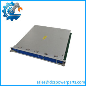
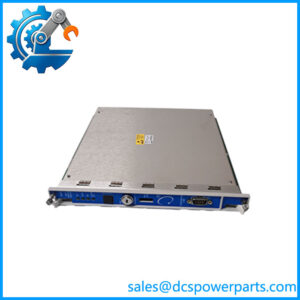
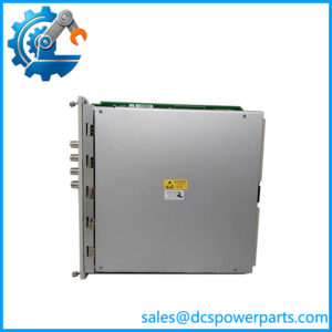
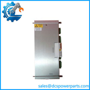
The Bently Nevada 3500/42M is a four-channel Proximitor Seismic Monitor used for continuous machinery condition monitoring. The 140482-01 is its Prox/Velom I/O module with external terminations, supporting compatible Prox/Accel and Velomitor transducers. The monitor conditions vibration-related signals and compares measured values against configured alarm setpoints.
For plants maintaining large rotating assets, the external-termination arrangement is particularly important during replacement work because the I/O architecture, termination hardware, and associated cabling must match. The 3500/42M also provides individual 4–20 mA recorder outputs and buffered transducer outputs for integration with plant monitoring equipment.
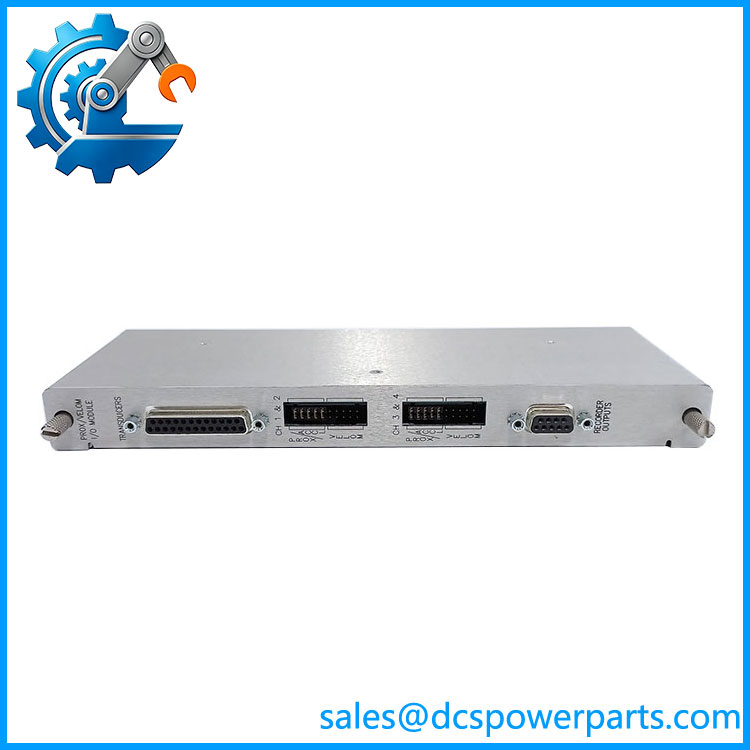
140482-01
Application Scenarios & Field Pitfalls
Engineering Pain Point
A common maintenance problem is finding a 3500 rack with a failed or suspect I/O module while the plant still has a healthy transducer installation in the field. Replacing the wrong I/O configuration can turn a straightforward module change into a wiring problem. With 140482-01, the critical detail is the external-termination architecture. The termination block and cable arrangement have to be checked before the replacement is installed.
Typical Applications
- Gas Turbine Plants — Radial vibration monitoring on turbine and compressor bearing housings.
- Steam Turbine Plants — Proximity-transducer monitoring for shaft vibration and machinery protection.
- Oil & Gas — Compressor and rotating-equipment vibration monitoring in continuous-process units.
- Power Generation — Continuous machinery protection using the 3500 rack as part of a turbine monitoring system.
The 3500/42M can be configured for measurements including radial vibration, thrust position, acceleration, velocity, eccentricity, differential expansion, shaft absolute measurements, and other supported monitoring functions. Channel configuration is performed in pairs, so the exact application depends on the installed configuration.
Technical Pitfalls to Avoid
- Do not confuse 140482-01 with 140471-01.
Both are Prox/Velom I/O modules, but 140471-01 uses internal terminations while 140482-01 uses external terminations. The termination hardware must match the I/O module. - Check the external termination block and cable before installation.
The OEM documentation lists dedicated external termination blocks and 129525/129529 cable assemblies. A module replacement is not complete if the associated termination arrangement is incompatible. - Verify the 3500 configuration and software revision.
The 3500/42M has specific firmware and 3500 software requirements depending on the monitoring functions being used. Do not assume that every firmware revision supports every legacy configuration.
Standard Operating Procedure (SOP) for Quality Control
For a replacement 3500/42M/140482-01 assembly, testing should focus on electrical condition, identification, rack compatibility, and signal behavior rather than simply confirming that the front LEDs illuminate.
1. Inbound Inspection
Each unit should be inspected before it enters stock:
- Verify the Bently Nevada identification and exact part number.
- Confirm 140482-01 rather than the visually similar 140471-01.
- Inspect connectors, pins, terminal interfaces, and mechanical guides.
- Check for oxidation, corrosion, contamination, cracked boards, or damaged housings.
- Record visible serial/identification information and revision markings.
- Compare the physical I/O arrangement against the intended 3500 rack configuration.
2. Live Functional Testing
Where the appropriate 3500 test equipment is available:
- Install the module in a compatible test rack.
- Verify rack communication and module status.
- Confirm the monitor’s OK and TX/RX status behavior.
- Apply suitable simulated or known-good transducer signals.
- Verify channel response and configured measurement behavior.
- Check the recorder output path where applicable.
- Confirm the external termination interface and associated cabling.
The 3500/42M provides buffered transducer outputs and individual +4 to +20 mA recorder outputs. The recorder outputs are proportional to the monitor full-scale value and support loads from 0 to 600 Ω.
3. Final Packaging
After testing:
- Seal the module in appropriate anti-static packaging.
- Protect connectors from mechanical impact.
- Attach the internal QC identification.
- Record test results against the part number and serial information.
- Package external termination accessories separately where supplied.
The objective is documented verification, not a claim that any electronic module can never fail after installation.
Frequently Asked Questions
Q1: Can Bently Nevada 3500/42M 140482-01 be directly replaced with 140471-01?
Not automatically. Both are Prox/Velom I/O modules, but 140482-01 uses external terminations, while 140471-01 uses internal terminations. The external termination block and cable arrangement therefore need to be checked before considering a substitution.
Q2: Is 140482-01 the main 3500/42M monitor?
No. This distinction matters.
The 3500/42M is the four-channel monitor, while 140482-01 is the Prox/Velom I/O module installed in the corresponding rear rack position. The OEM documentation lists 140482-01 separately as the Prox/Velom I/O module with external terminations.
Q3: What transducers can the 140482-01 support?
The OEM ordering information identifies Prox/Accel, Velomitor, or HTVS as supported transducer types for the 140482-01 configuration. The exact channel configuration still needs to be verified against the existing system documentation.
Q4: Can I hot-swap the 140482-01 while the 3500 rack is powered?
Do not treat this as a generic hot-swap operation. The 3500/42M monitor occupies the front slot while the I/O module occupies the corresponding rear slot, and the I/O wiring may be connected to live transducer circuits. In our experience, the correct procedure should follow the plant’s approved maintenance procedure and OEM documentation rather than assuming that removing a rear I/O module is electrically harmless.
Q5: Will replacing the 140482-01 erase my 3500/42M configuration?
The I/O module itself is not the place to assume that your complete rack configuration is stored. Configuration management belongs to the 3500 monitoring system and its configuration software. Before replacement, document or back up the existing rack configuration and verify channel assignments, alarm setpoints, transducer parameters, and measurement types.
Q6: What should I verify before ordering a replacement?
At minimum, verify these items:
- 3500/42M monitor configuration
- I/O part number: 140482-01
- External versus internal termination architecture
- Existing termination block part number
- Transducer type
- Cable length and cable assembly
- 3500 software/firmware compatibility
- Hazardous-area approval requirements, if applicable
The OEM lists external termination blocks separately from the I/O module and identifies specific cable assemblies for the external-termination arrangement.
Q7: What happens if the replacement fails during startup?
To be completely transparent, electronic replacement parts should be tested before installation whenever practical. If a unit does not initialize correctly, first isolate whether the fault follows the module or remains with the rack, termination wiring, transducer circuit, configuration, or power supply. A failed startup indication by itself does not prove that the I/O module is defective.
Engineering takeaway: For the Bently Nevada 3500/42M 140482-01, the part-number suffix is not a minor ordering detail. The 140482-01 external-termination configuration must match the installed termination hardware and field wiring. Verify the OEM documentation and existing rack configuration before installation.