Description
Key Technical Specifications
| Parameter | Specification |
|---|---|
| Product Model | IOM402 |
| Manufacturer | Lyngsø Marine / SAM Electronics |
| Part Number | 962.004.700 |
| System | EPS 2200-MAN Engine Protection System |
| Product Type | Digital input/output extension module |
| Digital Inputs | 16 channels |
| Input Isolation | Galvanically isolated |
| Input Voltage | 18–32 VDC |
| Input Current | 14–24 mA |
| Input Monitoring Current | 1.7–3 mA |
| Monitoring Resistance | 8.2 kΩ |
| Solid-State Outputs | 12 channels |
| Output Contact Type | Normally open |
| Output Rating | 60 V AC/DC, 3 A |
| Module Power Supply | Internal supply via X9 |
| Expansion Interface | X10 |
| Supported Extension Modules | DEM401, DRM401, DLM401, AAM401, VSM401 |
| Wire-Break Monitoring | Supported on inputs and outputs |
| Dimensions (D × W × H) | 125.4 × 216 × 67 mm |
| Mounting | DIN EN mounting rail |
| Operating Temperature | 0 to 55°C |
| Weight | Approximately 720 g |
| Marine Approvals | KR, ABS, DNV, GL, LR, RINA |
These values are documented in the SAM Electronics / Lyngsø Marine EPS 2200-MAN technical manual, document 810.001.070-01, dated October 17, 2008.
Product Introduction
Lyngsø Marine IOM402 Marine Automation I/O Module
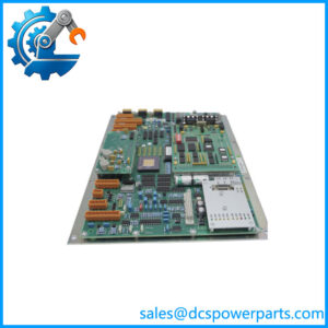
The Lyngsø Marine IOM402 is a 16-input, 12-output interface extension module used in the EPS 2200-MAN engine protection system. It provides galvanically isolated digital inputs and normally open solid-state relay outputs, with wire-break monitoring for connected signal circuits.
The module supports additional I/O expansion and uses a DIN-rail mounting arrangement. Its documented electrical ratings and marine approvals make it important to verify the exact module identity and installation configuration when maintaining an existing engine protection system.
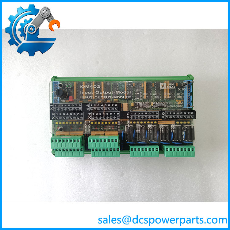
IOM402
Application Scenarios & Field Pitfalls (Engineer’s Perspective)
In a marine engine protection system, an I/O fault can affect alarm reporting, shutdown monitoring, or the availability of critical engine signals. The IOM402 must therefore be evaluated as part of the EPS configuration rather than as a generic PLC expansion card.
Typical application scenarios
- Main diesel engine protection: Collects digital signals associated with engine protection and operating conditions.
- Engine-room monitoring: Interfaces discrete equipment status and alarm contacts with the protection system.
- Shutdown and interlock circuits: Provides output switching for configured protection functions, subject to the approved system wiring.
- Marine control cabinet expansion: Adds digital signal capacity through the EPS system’s supported extension arrangement.
Field pitfalls to check before replacement
1. Input voltage and wire-break supervision: The documented input range is 18–32 VDC. The module also uses monitoring current and an 8.2 kΩ monitoring resistance. Incorrect field wiring or contact arrangements can generate wire-break alarms even when the external device appears operational.
2. Output load rating: The 12 normally open outputs are specified at 60 V AC/DC and 3 A. Check the actual load type, switching frequency, and external protection requirements before reconnecting actuators or relay circuits. Do not exceed the documented rating.
3. Expansion cable and module identification: The IOM402 connects through X9 and X10 arrangements. The EPS manual describes automatic module recognition and identifies flat-cable and connector faults as possible causes of lost module response. Inspect inter-module cables and plugs before concluding that the IOM402 itself has failed.
Related Products
The following modules are identified in the same EPS 2200-MAN documentation as components or supported extensions.
| Model | Product Description | Relationship |
|---|---|---|
| DZM402 | Speed relay module | Central EPS processing and speed-monitoring unit |
| FIM405 | 24 VDC filter module | Filters the system supply |
| DEM401 | Digital extension module | Listed extension |
| DRM401 | Digital relay module | Listed extension |
| DLM401 | Digital logic module | Listed extension |
| AAM401 | Analog acquisition module | Listed extension |
| VSM401 | Valve/status monitoring module | Listed extension |
| SEM402 | Serial interface module | Associated EPS system interface |
The extension relationships are documented in the EPS 2200-MAN manual. Confirm the actual cabinet configuration before treating any module as a replacement or interchangeable component.
Procurement and Quality Control Notes
The belongs to a legacy marine engine protection platform. Its documented association with EPS 2200-MAN makes accurate part-number and system identification especially important.
Before procurement, verify:
- The complete designation and part number 962.004.700.
- PCB and assembly revision markings.
- Condition of the six terminal strips.
- X9 power connection and X10 expansion connection.
- All 16 digital input channels.
- All 12 solid-state relay outputs.
- Wire-break monitoring performance.
- Compatibility with the installed DZM402 and EPS configuration.
- Available marine inspection and functional-test records.
Replacement warning: Do not confuse the with the DZM402. The DZM402 is the central speed-relay module, while the provides the additional digital input/output channels. They perform different functions within the EPS 2200-MAN system.