Description
Key Technical Specifications
| Parameter | Specification |
|---|---|
| Manufacturer | B&R |
| Model | 2EX302.5 |
| Module designation | EX302 |
| System platform | B&R SYSTEM 2010 |
| Module type | I/O module |
| Function | I/O bus expansion master |
| B&R ID code | $19 |
| Compatible backplanes | BP200, BP201, BP210 |
| Expansion interfaces | 2 slave connections |
| Transmission medium | Dedicated expansion cable |
| Supported cable lengths | 1 m or 2 m |
| Power consumption | Maximum 3 W |
| Dimensions | 285 × 40 × 185 mm |
| CE certification | Yes |
| UL certification | cULus E115267 |
Product Introduction
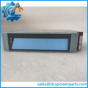
The B&R 2EX302.5 Expansion Master is designed to extend the local I/O architecture of B&R SYSTEM 2010 installations. Its main task is to divide the I/O bus into separate segments and connect expansion slave modules to the existing system. This arrangement supports distributed I/O placement within larger control cabinets and machine installations.
The EX302 provides two connections for EX301 expansion slaves. Each expansion slave establishes its own I/O bus segment, allowing the system architecture to accommodate additional I/O modules. The module operates as part of the existing B&R 2010 hardware structure rather than functioning as a standalone controller.
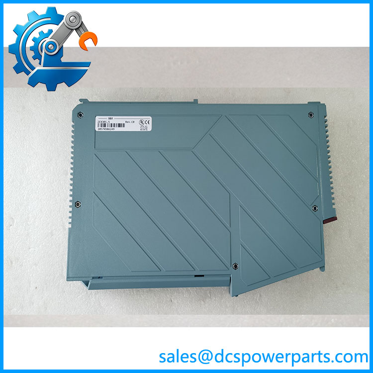
2EX301.5
Application Scenarios and Field Considerations
Typical applications
- B&R SYSTEM 2010 I/O bus expansion.
- Distributed I/O cabinet configurations.
- Legacy machine automation systems.
- Additional I/O segment integration.
- Industrial control-system hardware upgrades.
Important engineering checks
- Slave compatibility: Confirm that the connected expansion modules are EX301 units.
- Backplane selection: Verify the installed BP200, BP201, or BP210 backplane.
- Cable requirements: Select the correct 1 m or 2 m expansion cable.
- Bus topology: Review segment arrangement and module addressing before adding hardware.
- Power budget: Include the EX302’s maximum 3 W consumption in the I/O system calculation.
- Module recognition: Verify that all connected I/O modules are recognized after installation.
- Configuration backup: Preserve the existing controller and I/O configuration before changing the bus structure.
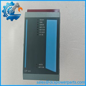
One specific diagnostic detail: the EX302 does not have operating or diagnostic status LEDs. Do not interpret the absence of indicator lights as evidence of module failure.
Related Products and Accessories
| Model | Description |
|---|---|
| 2EX301.5 | EX301 I/O expansion slave |
| 2BP200.4 | Single-slot I/O backplane |
| 2BP201.4 | Four-slot I/O backplane |
| 2BP210.4 | Single-slot I/O backplane with bus termination |
| 0G0010.00-090 | 1 m I/O bus expansion cable |
| 0G0012.00-090 | 2 m I/O bus expansion cable |
The EX301.5 is the corresponding expansion slave. The EX302.5 is the master and the EX301.5 is the slave; their functions are different, so they are not interchangeable.
Procurement and Quality Control
Before purchasing a replacement, verify:
- Complete part number:
2EX302.5. - EX302 module identification.
- Backplane compatibility.
- Condition of both expansion connectors.
- PCB condition and signs of overheating.
- Correct expansion cable length.
- Successful recognition of both slave connections during functional testing.
Lifecycle consideration
Secondary industrial inventory records report this model as discontinued. Confirm manufacturer support and replacement availability before planning a system expansion.
Advanced Search
Procurement recommendation: Specify B&R 2EX302.5 together with the required expansion cables and compatible backplane. Do not substitute the EX301.5, because it performs the slave function rather than the master function.