Description
Technical Specifications
| Parameter | Specification |
|---|---|
| Manufacturer | Yokogawa |
| Model | YS1700-100/A06/A31 |
| Product type | Programmable indicating controller |
| Controller family | YS1000 series |
| Control function | Programmable single-loop control |
Input option /A06 |
Isolated two-wire transmitter input |
Communication option /A31 |
RS-485 serial communication |
| Supported protocols | PC-link, Modbus, YS protocol, and peer-to-peer communication |
| Power supply | The -100 code indicates the 100 V AC / 24 V DC common power configuration |
| Operator interface | Front-panel display and keys |
| Programming | Function-block and text-based programming |
| Manual control | Hard manual unit is included for the applicable -1 model configuration |
| Ethernet | Not specified by /A31; Ethernet uses the separate /A34 option |
| Front-panel protection | IP54 for the applicable basic type |
| Exact electrical ratings | Confirm against the applicable general specification and nameplate |
The option-code definitions above are based on Yokogawa’s official YS1700 general specifications. The complete ordering code should be checked against the nameplate because suffix combinations and hardware variants affect compatibility.
Product Overview
The Yokogawa YS1700-100/A06/A31 is a programmable indicating controller intended for single-loop process control. It combines operator indication, configurable control logic, and output handling in a panel-mounted instrument. Depending on the application program, a YS1700 can be used for functions such as pressure, flow, level, or temperature control, provided the selected input hardware and control configuration are suitable for the process.
The /A06 option specifies an isolated two-wire transmitter input, making it relevant to applications using compatible loop-powered field transmitters. The /A31 option adds RS-485 communication, supporting PC-link, Modbus, Yokogawa’s YS protocol, and peer-to-peer communication. This can support data exchange with compatible supervisory or control equipment, but the actual communication settings, register mapping, and protocol configuration must match the connected system.
The -100 portion identifies the YS1700’s basic type and power-supply configuration in the model code: type 0, with 100 V AC / 24 V DC common power. The -1 use code denotes the version with a hard manual unit. These distinctions matter when replacing a controller in an existing panel, as the power supply, manual-control arrangement, input option, and communications interface must match the installation requirements.
Major Features and Advantages
Programmable single-loop control
The YS1700-100/A06/A31 supports user-defined control programs, allowing the controller to be configured for the process rather than restricted to a fixed-purpose indicating function. Yokogawa’s supports function-block programming as well as text-based programming compatible with earlier user programs.
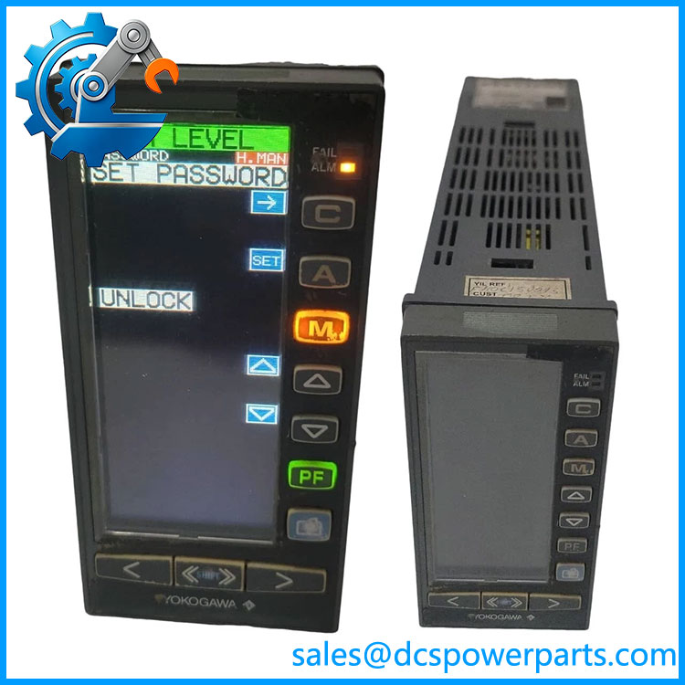
YS1700-100/A06/A31
Isolated transmitter input
The /A06 option is designed for two-wire transmitter input with isolation. This is important when integrating compatible field instruments into a control loop. Before commissioning, confirm the transmitter’s signal range, wiring arrangement, supply requirements, and the input characteristics specified in the controller manual.
RS-485 communication
The /A31 option provides serial communications using supported protocols, including Modbus and PC-link. This is useful when the controller must exchange process values or control data with compatible external equipment. Communication should be validated against the intended protocol, baud rate, station address, wiring polarity, and system-side configuration.
Manual-control capability
The -1 use code indicates a controller with a hard manual unit. Yokogawa describes hard manual control as an independent manual override intended to maintain operator control when certain control-circuit or CPU failures occur. It is not a substitute for an application-specific safety system or independent protective interlock.
Panel integration and configuration tools
The provides front-panel indication and parameter access, and can be configured using Yokogawa’s YSS1000 software. Before loading or transferring a program, retain a verified backup of the existing configuration and confirm compatibility with the target controller version.
Applications
The Yokogawa -100/A06/A31 can be applied to single-loop process-control duties in industrial plants, including compatible pressure, flow, level, and temperature loops. The actual application depends on the transmitter type, output device, control strategy, configured ranges, and engineering requirements. The controller’s programmable nature permits application-specific logic, but it does not establish suitability for every process or safety function.
The isolated two-wire transmitter input is relevant where a compatible field transmitter supplies a current signal to the controller. During commissioning, verify the loop wiring and signal scaling against the instrument datasheet. Check zero and span, engineering units, alarm limits, and control action before allowing the controller to operate the process.
The RS-485 option supports communication with compatible devices or supervisory systems. In a retrofit, confirm the required protocol and interface settings rather than assuming that a physical RS-485 connection guarantees interoperability. For direct communication with compatible Yokogawa CENTUM CS 3000 or CENTUM VP systems, Yokogawa’s documentation identifies /A31 as the applicable RS-485 option, subject to the system configuration.
For replacement projects, match the full controller code and verify the power supply, input option, communication option, manual-control configuration, and stored control program. A controller with a similar front panel may have different input or communication hardware and should not be substituted without an engineering review.
Related Products
| Model | Relationship |
|---|---|
| YS1500 | Related Yokogawa indicating controller in the YS1000 family. |
| YS1360 | Manual station for manipulated-variable setting; a related operator-control instrument. |
| YS110 | Portable manual station used for supported controller maintenance and replacement procedures. |
| YSS1000 | Yokogawa setting and programming software for YS1000-series instruments. |
| YS010 | Expandable I/O terminal used with applicable expandable-I/O controller configurations. |
| YS011 | Expandable I/O cable for the compatible YS010 arrangement. |
| -100/A34 | Different communication configuration using Ethernet/Modbus TCP; not the same as /A31. |
Verify each related product’s role and compatibility against the intended installation before ordering.
Installation and Maintenance
Before installing the -100/A06/A31, verify the full ordering code and the panel wiring. Confirm the supply arrangement, transmitter-input wiring, RS-485 connections, output wiring, and required mounting dimensions against the applicable Yokogawa documentation. Isolate power and follow site electrical-safety procedures before removing or connecting the controller.
Inspect the unit for damage to the housing, terminals, display, and front-panel keys. Check that field wiring is correctly identified and that serial communication wiring matches the approved drawing. Before removing an existing controller, record its configuration and retain a verified backup of the user program and operating parameters.
After installation, check power-up diagnostics and verify the transmitter input using a known signal or an approved loop test. Confirm the displayed process value, engineering-unit scaling, alarm behavior, and control output response under controlled conditions. Validate RS-485 communications independently by checking the protocol, address, baud rate, parity, and data mapping required by the connected equipment.
Do not return the controller to automatic operation until the control action, output limits, and manual-control behavior have been checked. Where the unit is part of a critical control loop, complete the site’s required functional testing and obtain the appropriate operational approval before restoring service.
Product Assurance
For procurement of the Yok/A06/A31, confirm the exact model code, condition, and available test evidence. The input and communications options are material to compatibility; a base-model match alone is not sufficient. If the controller is refurbished or used, request details of the inspection and functional checks performed, including whether the input and RS-485 interfaces were tested.
Check that the supplied unit’s label matches the quotation and that any warranty, return conditions, and lead time are documented. If the original controller’s program must be retained, confirm that a verified backup exists and that the target controller supports the required configuration.
Final acceptance should be based on the actual nameplate, applicable Yokogawa documentation, and commissioning results. Do not assume that the controller’s general capabilities confirm that a particular user program, communication map, or control-loop configuration will work without adjustment.