Description
Technical Specifications
| Parameter | Specification |
|---|---|
| Product Model | SDV144-S63 |
| Manufacturer | Yokogawa |
| Product Type | Digital input module |
| Number of Channels | 16 |
| Input Signal Type | No-voltage contact |
| Input ON Resistance | 1 kΩ maximum |
| Input OFF Resistance | 100 kΩ minimum |
| Input Current | 6 mA ±20% at 24 V DC and 0 Ω input |
| External Field Supply | 24 V DC, +20%/−10% |
| External Supply Capacity | 200 mA |
| Maximum Instantaneous Input Voltage | 30 V DC |
| Maximum Input Response Time | 40 ms |
| Isolation | Module isolation |
| Withstand Voltage | 2 kV AC for 1 minute, input-to-system, with the 16 inputs collectively connected |
| Current Consumption | Up to 290 mA at 5 V DC; up to 140 mA at 24 V DC |
| Connection | Signal cable interface adapter for Yokogawa-specific cable |
| Environmental Standard | ISA Standard G3 |
| Operating Temperature | −20°C to +70°C |
| Explosion Protection | Not provided in this configuration |
| Approximate Weight | 0.41 kg with signal cable interface adapter |
Specifications are compiled from available product listings and Yokogawa technical documentation. Confirm the applicable hardware revision and manual before using these values for engineering approval.
Product Overview
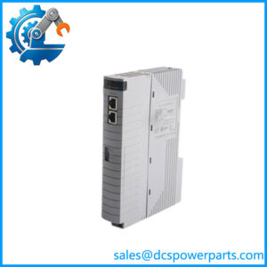
The Yokogawa SDV144-S63 is a 16-channel digital input module designed to interface no-voltage contact signals with compatible Yokogawa control-system I/O hardware. Typical signal sources include auxiliary contacts, relay contacts, equipment-running indications, and discrete status contacts from field devices. The module reads the open or closed state of each input, allowing the control application to use those states for status monitoring, interlocks, alarms, and sequence logic. Its input design is intended for dry contacts rather than direct connection to arbitrary powered digital signals.
The module provides module-level isolation between the input circuit and the system side. Published specifications list a maximum input response time of 40 ms and a 24 V DC external field supply. These characteristics matter when engineers evaluate signal timing, contact compatibility, and the relationship between field wiring and control-system logic. The response time should not be confused with the total time required for a signal to pass through the I/O subsystem, execute application logic, and trigger an output.
The -S63 suffix is important when sourcing a replacement. Available Yokogawa-related documentation identifies the S6 configuration as using a Yokogawa-specific signal cable interface adapter without explosion protection, while the final 3 indicates ISA Standard G3 environmental classification and a specified operating temperature range of −20°C to +70°C. This configuration is also listed as a replacement for the earlier SDV144-S33, but a substitution should be confirmed against the installed system, wiring arrangement, and approved parts list.
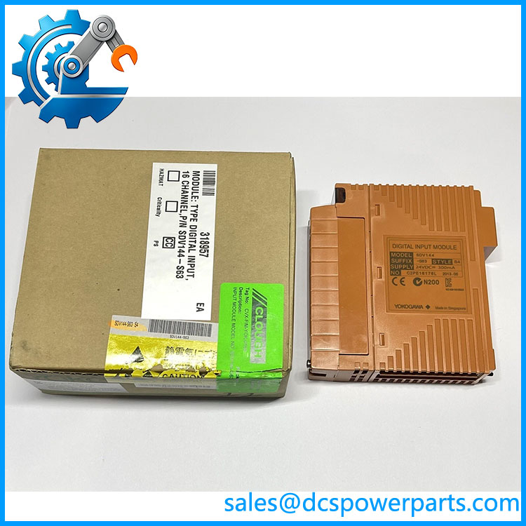
SDV144-S63
Major Features and Advantages
1. Sixteen discrete input channels
The SDV144-S63 supports 16 digital input points in one module. This allows multiple contact states to be collected at a single I/O location, helping organize equipment status and discrete process signals. The actual benefit depends on the control-system configuration and the number of available module positions.
2. Designed for dry-contact signals
The module is specified for no-voltage contact inputs. Published electrical limits include an ON resistance of 1 kΩ maximum and an OFF resistance of 100 kΩ minimum. These values provide a practical reference for checking field contact suitability. Do not assume that a 24 V powered output, transistor output, or externally energized signal can be connected directly without checking the manufacturer’s wiring requirements.
3. Module-level isolation
Module isolation separates the input circuitry from the system side. The published withstand-voltage specification is 2 kV AC for one minute between the input signal group and the system, with the 16 input lines collectively connected for the test. This is an isolation specification, not permission to apply that voltage during normal operation or a guarantee against every transient or wiring fault.
4. Signal cable interface adapter
The S6 configuration is associated with a Yokogawa-specific signal cable interface adapter. This is a hardware compatibility consideration, not simply a convenience feature. Confirm the cable type, mating terminal board or interface, connector arrangement, and cable length against the installed I/O design before purchasing a replacement.
5. Environmental suitability
The suffix 3 is associated with ISA Standard G3 environmental classification and a published operating range of −20°C to +70°C. This can be relevant in installations exposed to corrosive airborne contaminants, but G3 classification does not eliminate the need for suitable enclosure design, cabinet ventilation, contamination control, and site-specific environmental review.
6. Replacement planning
The SDV144-S63 is listed as a replacement for SDV144-S33. Treat that relationship as a sourcing lead rather than automatic proof of drop-in compatibility. Check the system hardware revision, connection method, configuration records, and any engineering change requirements before replacing a working module with a different suffix.
Typical Applications
- Equipment status monitoring: Reading dry-contact indications for motors, pumps, fans, and other equipment when the field device provides compatible contact signals.
- Process permissive logic: Supplying discrete contact states to control logic used to determine whether a process step or equipment start condition is satisfied.
- Alarm and event inputs: Collecting contact indications from compatible switches, relays, and alarm devices for processing by the host control application.
- Sequence control: Providing discrete feedback used by programmed sequences, subject to the scan timing and logic configuration of the complete system.
- Utility and auxiliary systems: Monitoring selected status contacts from support equipment such as ventilation, cooling, or power-distribution systems where the signal interface meets the module’s electrical requirements.
- Existing-system maintenance: Replacing a failed or suspect module in a compatible Yokogawa I/O installation, provided the part number, suffix, cabling, and configuration are verified.
These are application examples based on the module’s published dry-contact digital input function, not a statement that the module is independently certified for every listed application. For safety-related control functions, confirm the system architecture, applicable certifications, and approved module usage rather than relying on the product type alone.
Related Products
The following products are relevant when reviewing the same Yokogawa I/O family or planning associated signal interfaces.
| Model | Relationship |
|---|---|
| SDV144-S33 | Earlier configuration listed as replaced by SDV144-S63; confirm connection and environmental requirements before substitution. |
| SDV521 | Yokogawa digital output module for 24 V DC output applications; a different I/O function. |
| SDV526 | Digital output module for 100–120 V AC applications; not a replacement for a digital input module. |
| SDV531 | Digital output module for 24 V DC applications; used for output rather than contact-input acquisition. |
| SDV541 | Digital output module with 16 channels and 24 V DC output functionality. |
| SAI143 | Analog input module for 4–20 mA signals; relevant to mixed analog/digital I/O systems. |
| SAV144 | Analog input module for voltage signals; a different signal-processing function. |
| AKB331 | Yokogawa-specific signal cable family associated with the SDV144 connection configuration; confirm the exact cable variant and length. |
The related module functions and cable-family information are documented in Yokogawa I/O material. Physical fit, system support, and interchangeability still require verification for the specific installation.
Installation and Maintenance
Before installing a SDV144-S63, confirm the complete part number against the control-system bill of materials and the existing module label. Check that the target I/O subsystem supports the module and that the required signal cable interface adapter and Yokogawa-specific cable are present. Do not assume that a connector which physically fits establishes electrical compatibility.
- Isolate power safely. Follow the site’s lockout/tagout procedures and the applicable Yokogawa installation instructions before removing or inserting the module.
- Verify field signals. Confirm that each input is a compatible no-voltage contact. Check contact resistance and wiring condition before connecting the field circuits.
- Check the external supply. Verify that the 24 V DC field supply stays within the published range of +20%/−10% and has adequate capacity for the connected circuit.
- Inspect cabling and connectors. Look for damaged insulation, bent contacts, loose terminations, contamination, and signs of corrosion. Confirm the correct cable and interface arrangement.
- Validate channel mapping. Compare channel assignments and application logic with the approved drawings. A wiring or addressing mismatch can produce incorrect equipment status even when the module itself is functional.
- Test after installation. Exercise each relevant contact input and confirm that the expected state appears in the control system. Test alarms and interlocks using an approved commissioning procedure.
- Document the change. Record the installed model and revision, test results, wiring changes, and any updated configuration information.
For maintenance, investigate field wiring, external supply quality, connector condition, and configuration before concluding that the module has failed. If replacement is necessary, use a known-compatible part and follow the site’s change-control and commissioning requirements. The 40 ms maximum module response-time specification is only one component of end-to-end response; it does not replace a system-level timing assessment.
Product Assurance and Procurement Checks
When purchasing a Yokogawa , verify the identity and condition of the actual unit rather than relying on the model description alone. Ask the supplier to confirm the complete suffix, hardware revision where applicable, included adapter, and whether any required cable or accessory is supplied separately.
For a replacement intended for an operating plant, compare the proposed unit with the installed module and the approved spare-parts list. Confirm the supported I/O configuration, environmental requirements, field connection method, and any restrictions imposed by the control-system design. If the purchase is intended for a safety-related application, obtain the required documentation and confirm the module’s approved role in that system.
Incoming inspection should include a visual check for damaged connectors, corrosion, contamination, and signs of unauthorized repair. Where suitable test facilities and procedures are available, functional checks should verify representative input channels and confirm that their states are correctly reported. A visual inspection alone cannot establish full functionality, and a supplier’s description should not be treated as proof that a unit has been tested.
For used, refurbished, or surplus stock, establish the actual condition, test scope, traceability, and warranty terms before placing the order. For new stock, request confirmation of packaging and provenance where these are important to the site’s quality requirements. Do not assume availability, original packaging, or a particular warranty solely from the model number.
Procurement recommendation: Treat the as a specific 16-channel, 24 V DC dry-contact input configuration with module isolation and a Yokogawa-specific signal cable interface. Verify the suffix, adapter, cable arrangement, and host-system compatibility before approving it as a replacement.