Description
Technical Specifications
| Parameter | Specification |
|---|---|
| Product Model | SDV144-S13 |
| Manufacturer | Yokogawa |
| Module Type | Digital input |
| Number of Channels | 16 |
| Input Signal | No-voltage contact |
| ON Contact Resistance | 1 kΩ maximum |
| OFF Contact Resistance | 100 kΩ minimum |
| Input Current | 6 mA ±20% at 24 V DC with 0 Ω input |
| Contact Rating | 24 V DC (+20%/−10%), 10 mA or greater |
| External Power Supply | 24 V DC (+20%/−10%) |
| External Supply Current Capacity | 200 mA |
| Maximum Instantaneous Input Voltage | 30 V DC |
| Maximum Input Response Time | 40 ms |
| Withstand Voltage | 2 kV AC for 1 minute, input signal to system |
| Current Consumption | 290 mA maximum at 5 V DC; 140 mA maximum at 24 V DC |
| External Connection | Pressure-clamp terminal block or MIL cable |
| Environmental Classification | ISA Standard G3 |
| Operating Temperature | −20°C to +70°C |
| Approximate Weight | 0.36 kg for pressure-clamp terminal block or MIL cable configuration |
Specifications are based on available Yokogawa documentation and product references. Confirm the exact hardware configuration and installation manual before using these figures for engineering approval.
Product Overview
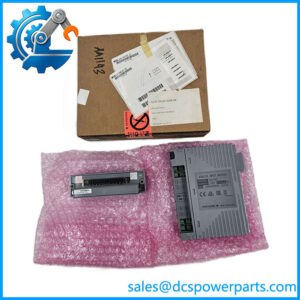
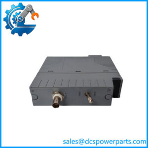
The Yokogawa SDV144-S13 is a 16-channel digital input module designed to acquire discrete signals from compatible field contacts. Typical signal sources include auxiliary relay contacts, equipment status contacts, limit switches, and other devices that provide a suitable no-voltage contact signal. The module converts those contact states into digital information for use by the host control system. Depending on the configured application, these signals may support equipment monitoring, alarm handling, permissive checks, and programmed operating sequences.
The module’s electrical specifications are important when assessing field compatibility. Published data gives a maximum ON resistance of 1 kΩ, a minimum OFF resistance of 100 kΩ, and an input current of 6 mA ±20% under the specified test conditions. The external supply is rated at 24 V DC with a tolerance of +20%/−10%. These limits should be checked against the connected contact devices and wiring design. A powered transistor output or an externally energized signal should not be assumed compatible with a no-voltage contact input without explicit confirmation in the applicable wiring documentation.
The S13 designation also matters when selecting a replacement. The configuration is associated with pressure-clamp terminal block or MIL-cable connections, with an ISA Standard G3 environmental classification and an operating range of −20°C to +70°C. Supplier references list SDV144-S53 as a replacement for the older SDV144-S13, but replacement suitability must be confirmed against the installed I/O system, cable and terminal arrangement, and project configuration. A shared base model does not, by itself, establish that two suffix variants are interchangeable.
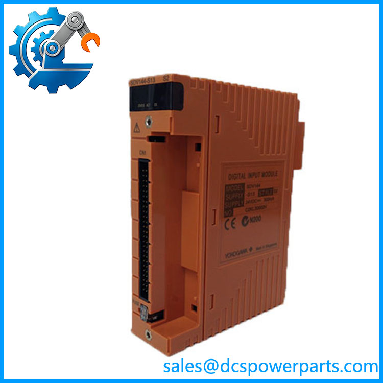
SDV144-S13
Major Features and Advantages
1. Sixteen digital input channels
The SDV144-S13 provides 16 digital input points in one module. This supports the collection of multiple field contact states within a single I/O location and can simplify channel organization in an established control cabinet. Actual channel assignment and application behavior depend on the host-system configuration.
2. Designed for no-voltage contact signals
The module is specified for dry-contact input applications. Its published ON and OFF resistance limits help engineers assess whether the connected contact devices meet the intended input requirements. Field devices must be evaluated using the correct wiring arrangement; a generic 24 V signal is not automatically equivalent to a compatible dry contact.
3. Defined response-time characteristics
The published maximum input response time is 40 ms. This is relevant when reviewing the timing of discrete status signals, alarm inputs, and sequence conditions. It is not the total response time of the complete control loop, which also depends on system scanning, application execution, communications, and any output devices involved.
4. Module-level isolation
Yokogawa describes the SDV144 family as a module-isolated digital input module. The specified withstand voltage is 2 kV AC for one minute between the input signal group and the system under the documented test arrangement. This is a dielectric withstand rating, not a normal operating voltage. It should not be interpreted as proof of independent galvanic isolation between every input channel.
5. Environmental classification for demanding installations
The 3 suffix is associated with ISA Standard G3 and a specified operating temperature range of −20°C to +70°C. This classification is relevant when assessing environmental conditions around the I/O cabinet. It does not remove the need for appropriate enclosure protection, ventilation, contamination controls, or site-specific environmental assessment.
6. Established I/O wiring options
The family supports different external connection arrangements, including pressure-clamp terminal blocks, MIL cables, and other configurations under different suffix codes. For the -S13, verify the existing wiring interface and any associated terminal board or cable before ordering. A module with a different connection suffix may require different interface hardware even if the core input function is similar.
7. Replacement planning for legacy installations
The -S13 is relevant to maintenance of installed Yokogawa digital I/O systems. A newer listed replacement may be suitable, but the decision should account for the exact I/O configuration, field wiring, system release, and environmental requirements. Verify the proposed substitute with the system documentation before scheduling a plant change.
Typical Applications
- Equipment status monitoring: Reading compatible dry contacts that indicate whether pumps, motors, fans, or auxiliary equipment are running or stopped.
- Process interlocks: Supplying discrete contact states to control logic used for permissives and operating-condition checks.
- Alarm acquisition: Collecting contact indications from alarm relays and compatible field devices for display and event handling.
- Sequence control: Providing status feedback for programmed equipment sequences, subject to the system’s configured timing and logic.
- Utility system monitoring: Acquiring discrete signals from support equipment where the contact characteristics meet the module’s requirements.
- Legacy DCS maintenance: Replacing a failed digital input module in an existing Yokogawa installation after confirming the full model and interface.
- I/O modernization projects: Assessing a listed replacement such as the -S53 where environmental classification or lifecycle considerations justify an engineering review.
These examples reflect the module’s documented digital input function. They do not establish that the module is independently safety-certified for every listed application. Any safety-related use must be checked against the system’s approved architecture and applicable certification documentation.
Related Products
| Model | Relationship |
|---|---|
| -S53 | Listed replacement refefor ; verify compatibility and configuration requirements before substitution. |
| -S33 | Related digital input configuration associated with Yokogawa-specific signal cables. |
| -S63 | Related configuration with a signal cable interface adapter and G3 environmental classification. |
| SDV541 | Yokogawa digital input module family member; verify channel type and exact specifications before selection. |
| SDV531 | Digital output module family member, intended for a different I/O function. |
| SDV521 | Digital output module for compatible configurations; not a replacement for a digital input module. |
| AKB331 | Yokogawa-specific signal cable associated with other connection configurations; confirm the required cable variant. |
These products are related through the Yokogawa digital I/O family, but they are not automatically interchangeable. The exact suffix, external connection, and system documentation determine suitability.
Installation and Maintenance
Before installing aawa , confirm the complete part number and inspect the existing module label. Check the terminal block or MIL-cable arrangement, external 24 V DC supply, field wiring drawings, and supported host I/O configuration. Do not assume that another suffix can be installed without checking the physical and electrical interface.
- Isolate the equipment safely. Follow site lockout/tagout and control-system maintenance procedures. Do not remove or insert the module under power unless the applicable system documentation explicitly allows it.
- Verify field contacts. Confirm that each connected device provides a compatible no-voltage contact signal. Check the wiring and contact condition before reconnecting the circuit.
- Check the external supply. Verify the 24 V DC supply is within the specified +20%/−10% range and that the available current capacity meets the circuit requirements.
- Inspect the interface. Check terminal connections, MIL connectors, cables, and insulation for looseness, corrosion, contamination, or physical damage.
- Confirm channel mapping. Compare field wiring and application channel assignments with the approved drawings. Incorrect mapping can produce misleading equipment status even when the module is functional.
- Test after installation. Exercise the relevant field contacts using an approved commissioning procedure and confirm that the expected states appear in the control system. Verify alarms and interlocks according to the site’s test plan.
- Document the replacement. Record the full model, hardware revision where available, test results, and any configuration changes.
If an input behaves incorrectly, investigate the field contact, wiring, external supply, terminal connections, and host configuration before declaring the module defective. Any diagnostic function requiring additional components should be implemented only according to the applicable Yokogawa documentation.
Product Assurance and Procurement Checks
For procurement, confirm theete designation and the required connection arrangement. Request clear identification of the offered unit, its condition, hardware revision where applicable, and the accessories included in the shipment. A listing that gives only the base model may not establish whether the supplied unit matches the installed wiring interface.
For used or refurbished stock, ask for the actual scope of inspection and functional testing. A visual check can reveal damage or corrosion, but it does not demonstrate that all 16 input channels operate correctly. Where the module is intended for an operating plant, incoming inspection and commissioning should follow the site’s approved procedures.
If a supplier proposes the -S53 as a replacement, verify the proposal against Yokogawa documentation and the plant’s approved spare-parts list. Check environmental requirements, terminal and cable compatibility, host-system support, and any configuration changes required before authorizing the substitution. Do not assume that a listed replacement is a guaranteed drop-in replacement in every installation.
Procurement recommendation: Theawa is a 16-channel, 24 V DC dry-contact digital input module. Confirm the complete suffix, wiring interface, environmental requirements, and replacement compatibility before ordering it for a live control-system installation.