Description
Product Overview
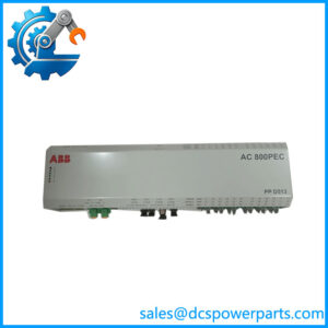
LD 810HSE Ex is the gateway between a FOUNDATION Fieldbus High Speed Ethernet subnet and the H1 segments where the instruments actually live. Four independent H1 links, each running at 31.25 kbit/s and each with this device acting as its Link Master, terminate on the left of the unit; one 10/100BASE-TX Ethernet port on the right carries everything upward to the HSE subnet, where an AC 800M with a CI860 interface — or a management console, or an asset-management server — picks it up. The device is registered as class 42c of the HSE profile, which is the formal statement that it does the full job: system and network management agents, an FMS server for object access into the H1 devices, cyclic publishing and subscribing, alarm and event distribution, and an SNTP server that keeps H1 timestamps aligned to the system clock.
Architecturally it is a bottleneck, and ABB designed it as one deliberately. Every value that travels from an H1 instrument to the control system passes through this single box, so the device’s published limits are not marketing figures but the actual shape of the funnel: 128 VCRs on any one H1 channel, 400 configured HSE VCRs, 64 H1-to-H1 republishing connections, and LAS schedules built from two schedules, four sub-schedules, 64 sequences and four elements per sequence. Designing a segment past those numbers produces a network that commissions and then behaves badly, which is why the numbers belong in the engineering package rather than in a footnote.
The Ex in the name describes the enclosure side, not the field side — and this is where secondary descriptions go most wrong. The device’s marking is Ex nA [ic] IIC T4 Gc for ATEX and IECEx, and Class I Division 2 Groups A, B, C, D for North America. It is a Zone 2 device. It is not Zone 1 equipment, it is not intrinsically safe apparatus, and the [ic] in the marking applies only to the FF-H1 interfaces. ABB also states plainly that the unit does not meet the impact-protection or IP54 requirements on its own, so it must be installed inside a protective enclosure that satisfies IEC/EN 60079-0 clause 26.4. A buyer who reads “Ex” and assumes the gateway can be hung on a wall inside the process area has bought the wrong product category.
The functional heart of the device sits on two boards. The LD Base Module carries the processor, the HSE port and the power and redundancy interfaces; a separate H1 Module daughterboard carries the four H1 channels. Both have their own hardware version and serial number, both are visible over the built-in web server, and firmware for the linking device and for the H1 power supply modules can be pushed over http or https. That two-board construction is also the spare-parts story: a failed H1 transceiver section does not require replacing the whole gateway.
Two limitations deserve to be stated at the outset because they decide upgrade projects. The second Ethernet socket, ETH2, is reserved for future use — it is not a redundant HSE port, despite what several listings claim. And ABB explicitly states that the LD 810HSE Ex is not suitable for replacing an earlier LD 800 linking device inside a redundant pair, so a plant planning to swap one half of an existing LD 800 pair has a different problem than a plant replacing a single non-redundant unit.
Technical Specifications
| Parameter | Value |
|---|---|
| Model and order code | LD 810HSE Ex, 3BSE091722R1 |
| Manufacturer | ABB |
| Product type | FOUNDATION Fieldbus HSE/H1 linking device |
| HSE profile registration | Class 42c |
| HSE interface | 1 × RJ45, 10BASE-T / 100BASE-TX (ETH1); ETH2 reserved |
| H1 interfaces | 4 channels, 31.25 kbit/s, FF physical layer type 114 |
| H1 bus voltage | 9–32 V DC, preferred 24 V DC |
| H1 channel output current | 10 mA per channel |
| Connection limits | 128 VCRs per H1 channel, 400 HSE VCRs, 64 H1-to-H1 republishing |
| Redundancy | Pair of devices plus dedicated RDL redundancy link |
| Power supply | 18–32 V DC, SELV/PELV mandatory, typ. 200 mA, max. 1 A |
| Coating and ingress protection | Conformal coating per ANSI/ISA-S71.04 G3, IP20 |
| Ambient and storage | −40 °C minimum operating, −40 to +85 °C storage, 10–95 % RH |
| Hazardous area approval | cULus Class I Div 2 A–D; ATEX/IECEx Ex nA [ic] IIC T4 Gc |
| Safety standards | IEC/EN/UL 61010-1, IEC/EN/UL 61010-2-201 |
| Dimensions and mass | 35 × 100 × 105 mm, 0.25 kg |
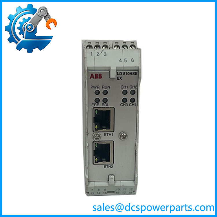
LD 810HSE EX 3BSE091722R1
Key Features and Advantages
A Link Master on every segment, not a transparent bridge: the LD 810HSE Ex runs the Link Active Scheduler on each of its four H1 links, so it owns the schedule that determines when each instrument publishes. That control is what makes deterministic cyclic data possible on H1 at all, and it is also why the LAS schedule parameters — two schedules, four sub-schedules, sequences and elements — have to be engineered rather than left at defaults.
Time distribution as a first-class function: the unit is an SM Time Publisher on the H1 side and an SNTP server on the HSE side, so alarm timestamps from four different segments line up with each other and with the control system. On a plant where a sequence of trips across several units has to be reconstructed afterwards, that alignment is the difference between a usable event list and a list of events that happened “some time around then”.
Republishing without a controller: process data can be republished from one H1 link to another, and from H1 to HSE and back, through publish/subscribe mechanisms that require no IEC 61131 controller configuration at all. Segment-to-segment interlocks that would otherwise need a PLC in the middle can therefore be built in the fieldbus layer — with the caveat that each such connection consumes part of the 64-connection republishing budget.
Redundancy built as a pair with its own wiring: two devices form one logical device. Both connect to the same HSE subnet and both connect their corresponding H1 ports to the same H1 link, and a separate redundancy link — RDL — runs between them with transmit and receive crossed. The primary runs the LAS and all communication; the secondary waits. One device can fail without stopping the segment, but the pair then operates non-redundantly until the failed unit is replaced and the set is restored.
Diagnostics over http, in plain sight: the built-in web server exposes general status, hardware versions and diagnostics from an ordinary browser on the same Ethernet segment, and firmware updates for the device and for the H1 power supply modules go through the same channel. What the device deliberately does not offer is SNMP, so network management platforms expecting an SNMP agent will find nothing to poll.
A footprint that respects a crowded cabinet: 35 mm wide on DIN rail, 0.25 kg, coated to ANSI/ISA-S71.04 G3 for the sulphur-bearing atmospheres common around process units, and rated down to −40 °C ambient. Mounting inside a protective enclosure in Zone 2 is the requirement, and the small footprint makes that enclosure practical.
Applications
Oil and gas production and processing: wellhead and gathering stations, separation trains and export metering, where H1 instruments on several segments must reach a central 800xA system over an HSE backbone without a marshalling cabinet full of analogue cards.
Refinery and petrochemical units: reactor and column instrumentation, valve positioners and analysers on H1, with the linking device sitting in a Zone 2 rack room and its protection dependent on the enclosure rather than on intrinsic safety in the field.
Chemical and pharmaceutical plants: batch and continuous units where FOUNDATION Fieldbus is used for its device-level diagnostics, and where alarms and events from H1 devices must arrive in the 800xA alarm management philosophy with correct timestamps.
Power generation: boiler and water-treatment segments, where the gateway’s −40 °C rating and conformal coating suit outdoor-adjacent and unheated enclosures.
Pulp and paper and metals: wet, dusty and sulphurous environments where the G3 coating and IP20-in-enclosure arrangement are the practical answer, and where H1 segments are distributed across a large site.
Brownfield upgrades replacing LD 800 units: single non-redundant gateways can be replaced by an LD 810HSE Ex with configuration taken over from the old device; redundant LD 800 pairs cannot, and must be handled as a pair replacement instead.
Related Products
LD 810HSE — the non-Ex version of the same linking device for safe-area installations. LD 800HSE Ex — the predecessor Ex-rated linking device this unit supersedes; still installed in many plants. LD 800HSE — the earlier non-Ex linking device, the common starting point for upgrades. CI860 — AC 800M HSE communication interface module that acts as HSE host on the subnet and is the usual upper connection. CI 940F (3BDH001015R0001) — AC 900F HSE/PROFINET interface module that explicitly supports FOUNDATION Fieldbus connected through the LD 810HSE or LD 800HSE. LD Base Module — the base module (motherboard) of the linking device, carrying the processor and HSE port; a separate spare item from the H1 section. H1 Module — the four-channel H1 daughterboard, replaceable independently of the base module. Redundancy link cable (RDL) — the dedicated cable connecting a redundant pair with crossed transmit and receive; required for correct role negotiation.
Installation and Maintenance
Before installation: confirm the area classification is Zone 2 and that a protective enclosure meeting IEC/EN 60079-0 clause 26.4 is available, since the LD 810HSE Ex relies on that enclosure for impact and ingress protection. Verify the 24 V supply is SELV/PELV within 18–32 V and sized for the 1 A switch-on surge rather than the 200 mA running current. Record the existing device’s IP settings, HSE configuration and LAS schedule before removal. In a redundant set, connect the RDL wiring and the Ethernet and H1 cabling before applying power — a unit powered without its redundancy link boots as an independent non-redundant primary, which is exactly the wrong role in a pair. Keep the H1 slot time below 50, otherwise inactivity on the link can exceed 200 ms and delay fault detection.
Maintenance practice: use the web server for routine health checks — hardware versions of the base and H1 modules, channel LEDs, and the redundancy role indicated by RDL — and keep the firmware of the device and the H1 power supply modules at a documented level, since both are updated through the same web interface. When replacing a unit, watch the segment LEDs move from red to blinking green as devices rejoin, and finish by initialising the device in Fieldbus Builder FOUNDATION Fieldbus so the address assignment and schedule are restored. Do not put an LD 810HSE Ex into an existing LD 800 redundant pair; replace the pair as a pair, and confirm the redundancy role of both units after the first power-up.
Warranty and Quality
Every LD 810HSE Ex with order code 3BSE091722R1 is supplied as ABB’s FOUNDATION Fieldbus linking device, with the HSE class 42c identity, the four H1 channels and the Zone 2 marking confirmed before dispatch — because the Ex designation is frequently misread as Zone 1 or intrinsic safety, and a wrongly specified gateway is a commissioning problem in a hazardous area. Units are inspected for terminal and RJ45 condition, DIN-rail clip integrity and enclosure damage, and where a test segment is available they are checked for HSE link behaviour and H1 channel activity. They carry a 12-month repair, replacement or refund commitment. Support covers what this device actually raises in the field: confirming Zone 2 and enclosure requirements, planning VCR and republishing budgets before a segment grows, configuring a redundant pair and its RDL link, replacing an LD 800 unit correctly, and advising on the two-board spare strategy so that a transceiver fault does not cost a whole gateway.