Description
Technical Specifications
| Parameter | Specification |
|---|---|
| Model | ANT502-50 S1 |
| Manufacturer | Yokogawa |
| Module type | Optical ESB bus repeater slave module |
| Communication system | Yokogawa ESB bus |
| Transmission medium | Optical fiber |
| Typical system role | Remote I/O communication extension |
| Compatible host equipment | ANB11 series optical ESB bus node unit; ANT10U repeater unit, subject to configuration |
| Transmission distance | Up to 5 km is reported for the ANT502 optical variant; verify the applicable fiber, connectors, and system configuration |
| Supply voltage | Not independently verified for this exact suffix |
| Power consumption | Not independently verified |
| Operating temperature | Not independently verified from an authoritative specification for this exact suffix |
| Physical dimensions | Published listings conflict; confirm against the module drawing before panel-layout work |
| Product condition | Must be confirmed for the individual unit |
The confirmed product identity is an optical ESB bus repeater slave module. Some reseller listings provide conflicting dimensions, power figures, and environmental limits, so those values should not be treated as verified engineering specifications without the applicable Yokogawa documentation.
Product Overview
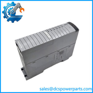
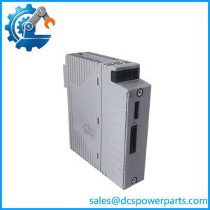
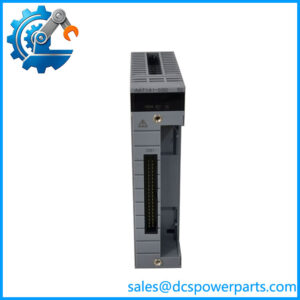
The Yokogawa ANT502-50 S1 is an optical ESB bus repeater slave module used in compatible Yokogawa distributed control system architectures. Its role is to support communication between ESB bus equipment across an optical link, allowing remote I/O nodes to be located farther from the associated control equipment than a short electrical connection would normally permit. This can be useful in large process plants where control rooms, equipment buildings, and field I/O cabinets are separated by long cable routes.
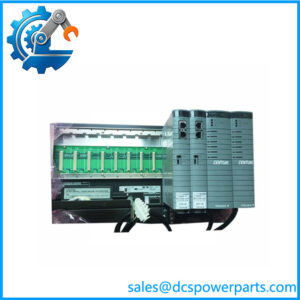
The module is associated with Yokogawa’s CENTUM VP and FIO-related system hardware. Published product information identifies the ANT502 family as an optical slave module that can be installed in an ANB11 optical ESB bus node unit or an ANT10U optical repeater unit, provided the host assembly and required connector options match the installation. The exact host slot, optical interface, and network arrangement should be checked against the system configuration rather than inferred from the model number alone.
For maintenance teams, the main concern is not simply whether the replacement module carries the same front-panel model label. The optical interface, host unit, connector arrangement, and control-system configuration must all match the installed hardware. Before replacing a failed unit, record the complete model and suffix, inspect the existing installation, and confirm the approved spare-part number against the site bill of materials or Yokogawa documentation. This reduces the risk of receiving a mechanically similar component that cannot be used in the intended node.
Major Features and Advantages
Optical communication for distributed I/O
The ANT502-50 S1 supports optical ESB bus communication in compatible Yokogawa control-system layouts. Fiber links can help connect remote I/O locations across long plant routes, reducing dependence on long electrical bus runs. The practical benefit depends on the approved topology, optical cable specification, and the other modules installed at each end of the link.
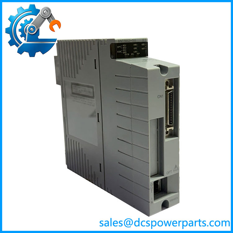
ANT502-50 S1
Slave-module role in the ESB network
This model is identified as a slave repeater, not a general-purpose Ethernet switch or an interchangeable optical transceiver. Its operation depends on compatible Yokogawa ESB equipment and the correct host assembly. Replacing it with a device intended for another communication protocol or network family is not an appropriate substitution, even if the physical connectors appear similar.
Support for separated equipment locations
Optical bus hardware is useful where remote I/O cabinets are installed away from the main control equipment. The ANT502 family is advertised for optical links of up to 5 km, but that figure should be treated as a system-dependent limit rather than a guaranteed distance for every installation. Fiber type, connector losses, link design, and the specific hardware configuration must be checked before commissioning.
Maintenance and replacement planning
Keeping the exact model and suffix on the site’s approved spare-parts list helps avoid delays during a communication fault. When purchasing a replacement, confirm the label, connector condition, host-unit compatibility, and the supplier’s test report. If the module is used or refurbished, ask whether it has been tested in a compatible host unit rather than only inspected visually.
Limits that should be verified
Detailed electrical ratings, power consumption, environmental limits, and physical dimensions were not consistently established by the available product listings for this exact suffix. Engineering decisions should use the applicable Yokogawa hardware documentation. Do not base cabinet design, power calculations, or acceptance testing on unverified reseller specifications.
Applications
CENTUM VP distributed control systems
The -50 S1 is relevant to compatible CENTUM VP installations that use optical ESB bus hardware to connect distributed I/O. In these systems, remote I/O communicates with the control architecture through the designated bus and node equipment. The repeater module supports the optical communication segment; it does not independently provide process control logic or replace an I/O module.
Remote I/O cabinets and equipment buildings
Process facilities often distribute I/O cabinets across different operating areas. Where the approved Yokogawa design calls for an optical ESB link, this module can form part of the communication path between the relevant node equipment. Typical considerations include the physical route of the fiber, separation between buildings, connector accessibility, and the need to maintain communication during planned maintenance.
Power generation and process industries
Power stations, chemical plants, and other continuous-process facilities may use distributed control architectures to monitor and operate equipment across a large site. In such environments, an optical bus repeater can be a maintenance spare for a designated communication node. Actual suitability depends on the installed system architecture; the product should not be assumed compatible with every Yokogawa controller, FIO assembly, or optical network solely because it belongs to the same manufacturer’s portfolio.
Corrective maintenance and planned replacement
When a communication fault is traced to the repeater module, replacement planning should begin by checking diagnostic alarms, link status, fiber integrity, and the associated host equipment. A failed link does not automatically prove that the module itself is defective. Damaged fiber, contaminated connectors, an incorrectly seated module, or a fault in the adjacent hardware can produce similar symptoms. Keeping a verified spare available can shorten recovery time, but the replacement should be tested against the actual system configuration before the original unit is removed from service.
Related Products
These products belong to the same general optical ESB bus or associated Yokogawa control-system environment. Their functions differ, so they should not be treated as direct substitutes without checking the system documentation.
| Model | Relationship to -50 S1 |
|---|---|
| ANT401-50 | Optical ESB bus repeater master module in the related ANT repeater family. |
| -5E | Related optical ESB bus repeater slave variant; verify optical and configuration differences. |
| ANT401-5E | Related master repeater variant; not automatically interchangeable. |
| ANT10U | Optical repeater unit that can accommodate supported repeater hardware. |
| ANB11 | Optical ESB bus node unit associated with the family. |
| ANB10 | Related Yokogawa ESB bus node hardware; verify supported module combinations. |
| CP471 | Yokogawa control processor associated with applicable CENTUM VP configurations, not a repeater replacement. |
The family relationships and host-unit associations are reflected in published product information, but exact compatibility must be checked against the site’s hardware revision and configuration.
Installation and Maintenance
Before installing -50 S1, confirm the full part number and suffix against the approved spare-parts list and the applicable Yokogawa hardware manual. Verify that the receiving ANB11 or ANT10U assembly supports the module and that the required ESB connector arrangement is present. Do not assume that a similar-looking ANT-series module has the same interface or installation requirements.
Follow the site’s electrical isolation and equipment-handling procedures before removing or inserting hardware. Inspect the module and its connectors for bent contacts, damaged housing, contamination, or evidence of moisture. Handle optical connectors carefully: dust or residue on the optical interface can degrade communication even when the module itself is functional. Use only approved fiber-cleaning methods and materials.
For fault diagnosis, check the system alarm history, node status, optical cable routing, connector seating, and the condition of adjacent repeater or node equipment. If the link remains unavailable after external checks, test with a known-good, configuration-matched spare where site procedures permit. Record the module’s original position and associated cabling before replacement so the installation can be restored accurately.
After installation, confirm that the node returns to the expected operating state and that communication alarms clear. Verify the relevant remote I/O status from the control system and document the replacement, observed fault, and test results. Do not claim successful restoration based only on front-panel indicators if the control system continues to report a communication fault.
Product Assurance
For procureme S1, verify the complete model marking, physical condition, and source of the supplied unit before committing it to a critical application. The available product listings identify it as a Yokogawa optical ESB bus repeater slave module, but they do not establish the condition or test history of any particular unit being offered.
A suitable incoming inspection should include:
- Part-number verification: Co S1 against the purchase order and approved spare list.
- Visual inspection: Check the housing, connectors, and labels for damage or alteration.
- Test transparency: Request the actual inspection or functional-test record and clarify whether testing was performed in a compatible host unit.
- Compatibility review: Confirm the intended ANB11 or ANT10U installation and applicable system configuration.
- Condition disclosure: Obtain written confirmation of whether the supplied unit is new, used, or refurbished, along with any applicable warranty terms.
For a plant-critical replacement, the lowest purchase price is not the only relevant factor. A module with an uncertain test history or unverified compatibility can introduce additional troubleshooting time during an outage. Confirm the required configuration and acceptance criteria before shipment, and retain the inspection records with the maintenance documentation.