Description
Technical Specifications
| Parameter | Specification |
|---|---|
| Manufacturer | Yokogawa Electric Corporation |
| Product Model | AAR181-S50 S2 |
| Product Type | RTD input module |
| Number of Input Channels | 12 |
| Supported Sensor | Pt100 RTD |
| Documented Wiring Type | 3-wire Pt100 |
| Measurement Current | 1 mA |
| Allowable Input Voltage | ±5 V DC |
| Allowable Wiring Resistance | 40 Ω or less per wire |
| RTD Accuracy | ±120 mΩ, per published specification |
| Temperature Drift | ±120 mΩ per 10°C |
| Field-to-System Isolation | 1500 V AC for 1 minute, per published module specification |
| Maximum Current Consumption | 450 mA at 5 V DC |
| Approximate Weight | 0.2 kg |
| Approximate Dimensions | 32.8 × 130 × 107.5 mm |
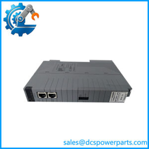
| Connection Type | Compatible RTD terminal block or dedicated cable interface |
| Installation | Supported Yokogawa FIO or other documented compatible I/O node |
These specifications are based on Yokogawa’s published AAR181 family information and corroborating technical listings. Verify the precise wiring, accuracy conditions, isolation arrangement, and connection accessories against the applicable manual before using them as acceptance criteria.
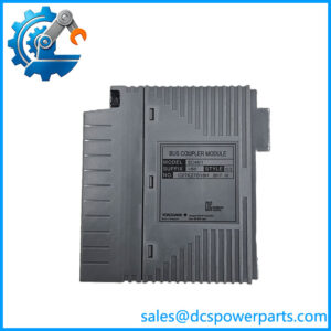
Model identification note: The documented AAR181 family is a 12-channel Pt100 RTD input module. The -S50 suffix is associated with the standard, non-explosion-protected configuration. The exact meaning of the additional S2 designation should be confirmed from the physical nameplate and applicable Yokogawa documentation rather than assumed to indicate a specific firmware or hardware revision.
Product Overview
The Yokogawa AAR181-S50 S2 is a 12-channel RTD input module designed to acquire temperature measurements from compatible resistance temperature detectors in industrial distributed control systems. It measures changes in sensor resistance and transfers the resulting measurement data to the control system for process monitoring, alarming, trending, and use in configured control strategies. Unlike a thermocouple input module, the AAR181 is intended for RTD-based measurement, with the documented sensor configuration centered on Pt100 devices.
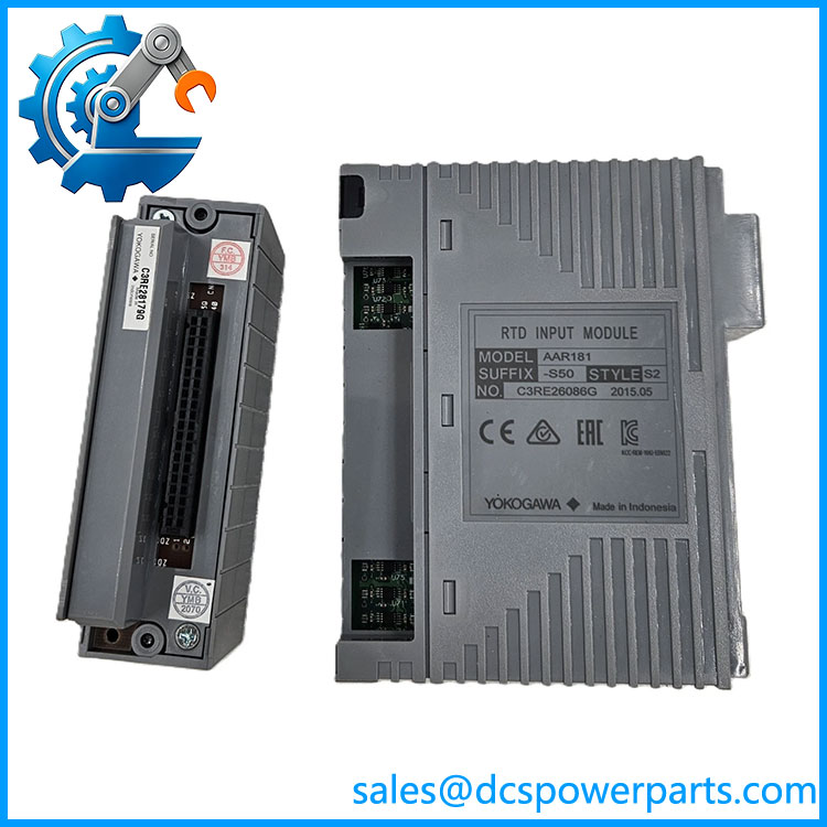
AAR181-S50 S2
The module’s 12-channel capacity allows multiple temperature points to be monitored through a single I/O module. Typical measurement points include process vessels, heat exchangers, piping, and equipment where a compatible Pt100 sensor is installed. The published specification identifies a 1 mA measurement current and an RTD accuracy of ±120 mΩ. Because resistance accuracy is not the same as a fixed temperature error across the entire operating range, engineers should consult the applicable Yokogawa specification for the relevant sensor curve, temperature range, and measurement conditions before assigning a temperature-accuracy figure.
The AAR181-S50 S2 is intended for use in compatible Yokogawa control-system I/O architectures. Its suitability depends on the host node, terminal arrangement, wiring method, and installed system configuration. Before ordering a replacement, verify the complete part number and the actual module’s condition. Do not assume that a thermocouple input module, a different RTD module, or a superficially similar variant is interchangeable without confirming the signal type and hardware requirements.
Major Features and Advantages
12-channel RTD measurement
The -S50 S2 provides 12 RTD input channels for compatible temperature sensors. This channel density can simplify cabinet layouts where multiple temperature measurements are required, while keeping the field wiring and channel assignment organized within the intended I/O architecture.
Pt100 sensor compatibility
The documented input function supports Pt100 RTDs, including three-wire configurations. Three-wire measurement helps compensate for lead-wire resistance when correctly wired and configured. The sensor type, wiring arrangement, and terminal connections must match the applicable Yokogawa documentation; do not assume support for every RTD type or wiring mode without checking the manual.
Defined excitation and resistance limits
The module uses a documented measurement current of 1 mA. The published allowable wiring resistance is 40 Ω or less per wire, and the allowable input voltage is ±5 V DC. These limits matter when evaluating long cable runs, wiring condition, and sensor-loop compatibility. Excessive lead resistance or poor terminal contact can produce measurement errors even when the module itself is functioning correctly.
Isolation and electrical protection
The published specification identifies a field-to-system withstand rating of 1500 V AC for one minute. This is a withstand-test rating, not a permissible continuous operating voltage. Engineers should verify the exact isolation arrangement and any grounding or hazardous-area requirements before installation. The standard -S50 configuration should not be treated as explosion-protected equipment.
Compact I/O integration
The module is designed for supported Yokogawa I/O node hardware, with compatible terminal blocks or dedicated cable interfaces depending on the installation. Maintaining the original connection arrangement can reduce wiring changes during a replacement, but accessory compatibility must be confirmed for the exact module and node.
Maintenance-oriented replacement
A correctly matched module can help restore temperature acquisition without redesigning the existing I/O architecture. That benefit depends on matching the model, host node, connection hardware, and configuration. A matching label alone does not prove that a used or surplus unit has been functionally tested.
Applications
The Yokogawa -S50 S2 is suited to temperature-monitoring applications using compatible Pt100 resistance temperature detectors. Typical process-industry applications include monitoring temperatures in vessels, pipelines, heat exchangers, and equipment where the installed sensor and wiring arrangement match the module’s documented input requirements.
In a process plant, RTD inputs often provide measurements used by operators to track process conditions and by controllers to execute configured control strategies. For example, a Pt100 sensor installed on a heat exchanger can provide temperature data for trending and alarm monitoring. The module acquires the sensor signal, while the control system applies the configured scaling, limits, and control logic. Correct sensor installation and channel configuration remain essential to obtaining a meaningful process value.
The module can also be relevant to maintenance projects involving replacement of a failed temperature input channel or restoration of an existing I/O node. Before replacement, technicians should establish whether the fault originates in the RTD element, field cable, terminal connection, node interface, or input module. An open sensor circuit or unstable reading does not automatically indicate a defective module.
For new or modified measurement points, engineering personnel should confirm the Pt100 sensor specification, lead-wire resistance, terminal arrangement, and required measurement accuracy. If the application requires a thermocouple, Pt1000 sensor, or a different wiring arrangement, verify support from the appropriate module documentation rather than selecting the solely because it is a temperature input device.
For spare-parts planning, record the complete model and suffix, host node type, connection accessories, and actual unit condition. This information helps procurement select a compatible replacement and gives maintenance teams a clear basis for testing the module after installation.
Related Products
| Model | Relationship |
|---|---|
| -S50 | Base RTD input module designation |
| AAR145-S50 | Related RTD/potentiometer input module family |
| AAT141 | Thermocouple/mV input module; different sensor input function |
| AAT145 | Isolated thermocouple/mV input module |
| AAI143 | Analog current input module for 4–20 mA signals |
| AAI135 | 8-channel isolated 4–20 mA input module |
| AAV144 | 16-channel isolated voltage input module |
| ATR8S | Compatible RTD terminal block option listed for the family |
| ATR8D | Dual RTD terminal block option listed for the family |
These products are related by temperature measurement, analog input function, or connection hardware. They are not all direct substitutes fo S2. Confirm the terminal block and cable compatibility in the applicable Yokogawa documentation.
Installation and Maintenance
Before installin S2, confirm the full model designation and the host I/O node. Check the field wiring drawings, terminal block or cable interface, sensor type, and channel assignment. Verify that the installed RTDs and wiring method match the module’s documented input requirements.
Follow the site’s approved isolation and lockout procedures before disconnecting field wiring. Label each sensor circuit and record its channel number before removal. Inspect the sensor cables and terminals for loose connections, corrosion, damaged insulation, and incorrect lead placement. For three-wire Pt100 measurements, verify that the three conductors are correctly identified and connected; wiring errors can introduce temperature offsets or unstable readings.
Check that the sensor and field wiring remain within the documented input and wiring-resistance limits. Do not assume that a different terminal block or cable adapter is compatible merely because it fits mechanically. Where hazardous-area instrumentation is involved, follow the approved system design and confirm that all required barriers and protection methods are suitable for the installation.
After installation, test representative channels using an approved RTD simulator or calibrated resistance source. Confirm that the control system displays the expected temperature, that channel scaling and alarms are correct, and that open-circuit conditions are handled as intended. If readings are inaccurate, check the sensor, lead resistance, terminal connections, and configuration before attributing the problem to the module.
Record the replacement part number, connection accessories, test results, and any configuration changes in the maintenance history. Use the applicable Yokogawa manual for final commissioning and acceptance criteria.
Product Assurance
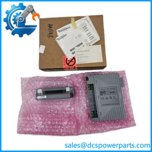
For the Yok S2, product assurance should begin with exact model identification and compatibility checks. Request clear photographs of the nameplate, connectors, and overall condition. Compare the full suffix and connection arrangement with the installed module and the site’s spare-parts records before accepting the replacement.
Published family specifications establish the module’s intended RTD input function, but they do not establish the condition of a specific unit. New surplus, used, and refurbished modules should be described accurately. Any functional-testing claim should identify what was tested, the test method, and the results available for review.
For critical temperature measurements, request test records where available and confirm warranty terms, return conditions, and delivery lead time. If a different suffix or module style is offered, obtain documented compatibility confirmation before accepting it as equivalent. Visual inspection alone does not demonstrate accurate resistance measurement or correct channel operation.
Final acceptance should consider the complete part number, host-node compatibility, sensor and wiring requirements, physical condition, and available test evidence. These checks reduce the risk of installing a module that fits the node but fails to meet the measurement requirements of the process.