Description
Key Technical Specifications
| Parameter | Specification |
|---|---|
| Product model | MRR1-D |
| Manufacturer | Woodward / SEG Electronics |
| Product series | High Tech Line MRR1 |
| Product type | Multifunctional generator rotor protection relay |
| Mounting | Flush mounting |
| Housing width | 12 TE |
| Rotor insulation measurement voltage | ±24 V |
| Insulation measurement frequency | 0.51 Hz |
| Insulation resistance range | 1 kΩ–1 MΩ |
| Maximum insulation input voltage | 600 VDC |
| Excitation current measurement | Galvanically isolated |
| Excitation current nominal value | 10 A DC |
| Excitation current measurement range | Up to 25 A DC |
| Maximum continuous excitation current | 20 A DC |
| Excitation current circuit burden | Less than 1 VA |
| Output relays | 5 |
| Programmable output relays | Relays 1–4 |
| Self-supervision relay | Relay 5 |
| Serial communication | RS-485 |
| RS-485 slave address | 1–32 |
| Minimum operating time | ≤100 ms |
| Return time | ≤30 ms |
| Operating temperature influence | ±2.5% from -20 to +70 °C |
| Weight | Approximately 1.5 kg |
| Auxiliary supply | Ordering-dependent; verify the complete type designation |
The technical values above are from the Woodward MRR1 manual. The manual’s order form lists 24 V and 110 V auxiliary-voltage versions, with AC/DC permissible ranges defined by the corresponding supply option. Do not select a replacement based only on the MRR1-D housing suffix.
Product Introduction
The Woodward MRR1-D is a flush-mounted multifunctional protection relay for synchronous generator rotor and excitation systems. It monitors rotor winding insulation resistance, excitation DC current, and current ripple associated with rotating rectifier diode failures. Its protection functions include rotor earth-fault warning and trip stages, excitation overcurrent and undercurrent supervision, and diode-failure detection.
The relay is intended for generator and synchronous-motor applications where rotor insulation and excitation-system condition require continuous supervision. It provides five output relays, programmable alarm and trip assignments, a front-panel display, and RS-485 communication for remote interfacing.
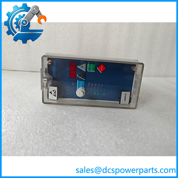
MRR1-D
Application Scenarios & Field Pitfalls
A rotor earth fault can remain undetected after the first insulation failure because the initial fault may not immediately interrupt generator operation. A second earth fault, however, can short part of the field winding and cause serious rotor damage. The MRR1 addresses this risk by measuring insulation resistance while also monitoring excitation current and rectifier ripple.
Typical application areas
- Synchronous generators: Rotor winding insulation supervision and excitation-system protection.
- Power generation plants: Alarm and trip signaling for rotor earth faults and excitation abnormalities.
- Industrial synchronous motors: Monitoring of field winding insulation and excitation current.
- Brushless excitation systems: Detection of excitation overcurrent, undercurrent, and rotating diode failures.
Field pitfalls
1. Verify the auxiliary supply version. The order form provides different auxiliary-voltage options. Confirm the installed supply rating from the nameplate before energizing a replacement. The D suffix specifies flush mounting; it does not identify the supply voltage.
2. Check the excitation-current measurement circuit. The relay uses a galvanically isolated measurement input, with a nominal current of 10 A DC and a measurement range up to 25 A DC. Confirm the wiring and actual excitation-current range before commissioning.
3. Preserve rotor insulation measurement connections. The low-frequency ±24 V test signal is applied to the field winding through the specified connection arrangement. Incorrect terminal connections can compromise the insulation-resistance measurement. Follow the wiring diagram, especially when only one end of the field winding is accessible.
Multifunctional Generator Rotor
4. Test the output-relay assignments. Relays 1–4 can be assigned to warning and trip functions, while relay 5 provides self-supervision status. Record the original assignments and verify the external trip circuits before performing relay tests. Isolate breaker trip circuits when testing could cause an unintended trip.
Multifunctional Generator Rotor
Related Products
- -A — rotor protection relay in a 19-inch rack-mount housing; the
Asuffix identifies the rack version. - — Base multifunctional generator rotor protection relay designation; the complete ordering code determines housing and electrical options.
- MRQ1 — Generator loss-of-excitation protection relay; its protection function differs from the rotor and excitation monitoring functions.
- MRP2-3IU — Directional power protection relay with three current and three voltage transformer inputs.
- MRP2-R3IU — Related directional power protection relay configuration with three current and three voltage inputs.
- XR1 — Rotor earth-fault protection relay from Woodward’s Professional Line; its function and hardware arrangement differ from the .
These devices belong to related generator and power-system protection product families, but they are not direct electrical substitutes.
Procurement note: For an -D replacement, verify the auxiliary voltage, RS-485 option, flush-mount housing, terminal arrangement, and existing protection settings. The original relay’s insulation-resistance thresholds, excitation-current thresholds, trip delays, and output assignments should be recorded before removal.