Description
Product Overview
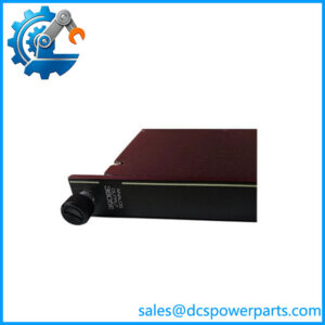
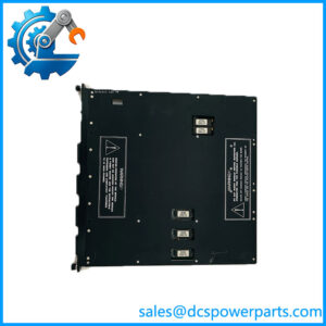
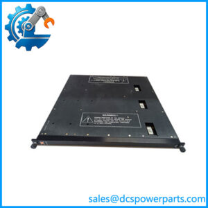
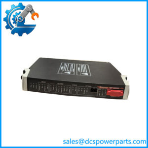
DI2301 7400208-020 is the digital input carrier of the Trident safety controller: Model 2301, a baseplate that terminates thirty-two discrete points and takes a single Model 3301 Digital Input Module in one of its two slots. The first thing worth establishing is what the label actually says. This ordering number is printed in the field as 7400208B-020 or 7400208C-020, with the letter between the body and the suffix, and the shortened 7400208-020 form is what circulates in marketplace listings and email enquiries. The letter variants are baseplate versions of the same Model 2301 kit; if a quote or a pick list shows the number without a letter, that is a transcription rather than a product, and the label on the item is the authority.
The second thing worth establishing is that the baseplate is not a mounting bracket with terminals on it. Triconex publishes the Model 3301 digital input impedance twice: more than 30 kΩ without baseplate, and approximately 3 kΩ with baseplate. That single line explains the whole part. The carrier supplies the field-side loading and threshold network, and at 24 VDC a 3 kΩ input draws about 8 mA — a real wetting current that keeps ordinary silver contacts clean and lets the module resolve an open circuit. Thirty-two points at that current is roughly 256 mA through the common return, and the published 0.2 W per point at 24 VDC (0.5 W at 33 VDC) is consistent with exactly that arithmetic. A baseplate that is substituted or bypassed changes the electrical behaviour of every point on it.
The input specification is built around plant reality rather than datasheet idealism. Operational range is 15 to 30 VDC against a 24 VDC nominal, with 33 VDC absolute maximum and −0.6 VDC reverse tolerance; the off region is 0 to 5 VDC, the transition region 6 to 14 VDC, and the on region 15 to 30 VDC. That 6 to 14 VDC band is deliberately wide, because long runs from a field switch carry voltage drop, and because a supply sagging to 18 VDC at the end of a cable must not read as a half-pressed contact. Input delay is under 10 ms in either direction, with a 6.4 ms time constant and a 3 dB point at 25 Hz — slow enough to reject contact bounce and electrical noise, fast enough for any interlock a safety system cares about.
Diagnostics are continuous and unusual in their honesty: the module keeps verifying its own ability to detect a transition to the opposite state, rather than only reporting the state it currently sees. A channel that can no longer see a change is a channel that will miss a trip, and the specification addresses that failure mode explicitly. Each I/O set carries an active and a hot-spare module, modules are mechanically keyed, and all field wiring lands on the carrier — so a module replacement breaks no conductor.
The kit is what the plant needs beyond the bare board: the I/O interconnect assembly 2921 that carries I/O messages and logic power between baseplates, the slot cover 2900 and the terminal cover 2901 that keep dust, liquids and corrosive atmosphere out of an unpopulated or partially wired position. The baseplate sits on the standard 178 × 249 mm I/O footprint, with terminals accepting 24 to 12 AWG, and the packaged one-module-plus-one-carrier form is the 5301 Digital Input TriPak.
Where the wiring cannot come straight to the baseplate — a hazardous area, or a marshalling scheme with field cable brought to a separate panel — the same module moves to the DI external termination baseplate, used with the 9573-610 hazardous-location termination panel. The baseplate in hand, though, is the direct-termination type: field conductors land on it.
Reseller pages on this number are unreliable in a specific way. DI3301 is described on one site as a TMR digital I/O module supporting Ethernet-APL, with a supply quoted as “100–400A1P” and an output frequency of 350 kHz; the same page lists D28799-005 in the same breath. None of it applies. Another page sells the baseplate as a “digital input module” outright. The reliable rule for this family is that the module number (3301) and the baseplate number (2301) are different items, and neither is a field I/O block with a DIN clip.
Technical Specifications
| Parameter | Value |
|---|---|
| Model and identity | DI2301 = Trident Model 2301 Digital Input Baseplate Kit; ordering number 7400208B-020 / 7400208C-020 (short form 7400208-020); baseplate assembly number 3000673-020 |
| Manufacturer / platform | Triconex, Invensys; now Schneider Electric — Trident (Trident v2) TMR safety controller |
| Item class | Digital input baseplate kit — passive carrier with field terminals and input conditioning |
| Points and module | 32 points, commoned; accepts one Model 3301 Digital Input Module per slot; 2 slots (L and R) with active / hot-spare |
| Input specification | 24 VDC nominal; operational 15–30 VDC; absolute maximum 33 VDC; reverse −0.6 VDC |
| Input thresholds | 0–5 VDC = off region; 6–14 VDC = transition region; 15–30 VDC = on region |
| Input impedance | > 30 kΩ without baseplate; approximately 3 kΩ with baseplate (about 8 mA per point at 24 VDC) |
| Input delay and bandwidth | < 10 ms on-to-off and off-to-on; time constant 6.4 ms; −3 dB at 25 Hz |
| Point loading | 0.2 W per point at 24 VDC; 0.5 W per point at 33 VDC |
| Diagnostics | Continuous verification that the module can still detect a transition to the opposite state; fault reported per channel |
| Isolation | Functional earth to protective earth 500 VDC min; functional earth to functional earth (logic) 800 VDC min |
| Kit contents | I/O baseplate; I/O interconnect assembly 2921; slot cover 2900; terminal cover 2901 |
| Terminals and dimensions | Compression terminals 24–12 AWG (0.2–3.3 mm²); baseplate 178 × 249 mm; module 44 × 220 × 169 mm; 70 °C maximum ambient |
| Power and packaging | Logic power from the MP baseplate, 24 VDC (19.2–30 VDC), under 3 W per I/O module; 5301 Digital Input TriPak (3301 + 2301); system limit 14 I/O modules, 10 with AO or PI |
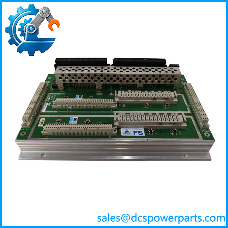
TRICONEX DI2301 7400208-020
Key Features and Advantages
The burden is on the carrier, and the numbers prove it: more than 30 kΩ without a baseplate and about 3 kΩ with one. That is not a detail for the datasheet’s footnotes — it is the reason a contact reads reliably at the end of a two-hundred-metre run, and the reason a substituted carrier changes every point on the position.
Wetting current by design: roughly 8 mA at 24 VDC through each point keeps silver contacts from building the film that turns a limit switch into an intermittent fault. Thirty-two points drawing that current is a load to plan — about 0.2 W per point, 256 mA on the common return — not a figure to discover when a shared 24 VDC supply browns out.
Thresholds that tolerate a sagging supply: the 6 to 14 VDC transition band and the 15 VDC on-threshold mean a switch circuit that loses four or five volts over distance still reads as closed. A narrower threshold design would call that a fault at exactly the moment the field wiring is fine.
Ten milliseconds of deliberate patience: the input delay and 25 Hz bandwidth reject contact bounce and drive-induced noise while staying far inside any interlock timing a safety system needs. Contacts that chatter on a vibrating skid stop producing phantom transitions.
Diagnostics that test the ability to see, not just the state seen: the module continuously verifies that it can still detect a transition to the opposite state. That is the failure mode that matters — a channel stuck in a plausible reading — and it is specified rather than assumed.
Wiring that stays with the plant: all terminals on the carrier, modules keyed, active and hot-spare in each set. Replacing a module is a lift-and-seat; replacing a carrier is a deliberate act with the wiring schedule in hand.
Complete kit, real protection: interconnect 2921, slot cover 2900 and terminal cover 2901 arrive together. In a plant atmosphere, an uncovered slot or terminal block is where corrosion starts and where the next fault comes from.
Honest limits: commoned points with no per-point isolation, one module per slot, and no analogue capability. Where signals float or need isolation per channel, this is the wrong carrier, and no configuration changes that.
Applications
Emergency shutdown input scope: pressure switches, level switches, valve position limits and permissives wired directly to the carrier, thirty-two points per position, in cabinets where the field cable arrives at the baseplate terminals and the marshalling is the terminal block itself.
Burner management and furnace panels: flame status, purge and low-fire proving switches, fuel-valve position feedback — circuits that run long distances from the burner front, where the 15 VDC on-threshold absorbs voltage drop that would otherwise produce a false “not proven”.
Compressor and turbine auxiliary skids: lube-oil pressure switches, vibration trip contacts, and rundown and overspeed discrete signals, on a platform where the 25 Hz input bandwidth keeps vibration-induced contact chatter out of the trip logic.
Water and wastewater stations: float switches, pump run-status and interlock contacts in panels where the point count is modest and direct termination keeps the marshalling simple and inspectable.
Legacy Trident columns under spares management: 7400208B-020 and 7400208C-020 appear in installed-base records and purchase orders, and matching the letter variant to the position — not just the body number — is what keeps a replacement consistent with the original build.
Hazardous-area or marshalled schemes: where field wiring must terminate at a separate panel, the same Model 3301 module moves to the DI external termination baseplate with the 9573-610 panel. This article’s carrier is the direct-termination route, and knowing which one a cabinet uses decides whether a spare will fit.
Related Products
3301 Digital Input Module — the module this carrier serves; 32 commoned points, three isolated channels, continuous transition-detection diagnostics; sold with the carrier as the 5301 Digital Input TriPak. 5301 Digital Input TriPak — packaged one-module-plus-one-baseplate combination, the standard ordering route for this pair. 9573-610 DI Hazardous Location Termination Panel — used with the DI external termination baseplate where field wiring must leave the cabinet. 7400210-020 Model 2361 AI/DI Baseplate Kit — the mixed carrier, 16 discrete points and 16 analogue points on one baseplate, when a position must serve both classes. 7400209-030 Model 2401 Digital Output Baseplate Kit — the output counterpart; note that the output carrier’s terminals are not interchangeable with input wiring. 7400210-010 Model 2351 Analog Input Baseplate Kit — the analogue carrier on the same 178 mm footprint, with its own 250 Ω burden. 2921 I/O Interconnect Assembly — the passive link carrying I/O messages and logic power between baseplates in a column. 2281 I/O Bus Extender Module Kit — carries the I/O bus to a second column, required beyond eight baseplates end-to-end or 200 m of bus. 2900 / 2901 Slot and Terminal Covers — the protection items in this kit; a position left uncovered is a future corrosion fault.
Installation and Maintenance
Before installation: read the label, not the enquiry — confirm 7400208B-020 or 7400208C-020 with the letter variant present, and confirm it is the 2301 digital input carrier rather than the 2361 mixed carrier sitting one digit away. Check the kit for interconnect 2921, slot cover 2900 and terminal cover 2901, confirm a Model 3301 module and matching keying, and establish that logic power reaches the position through the interconnect chain. Verify that the point count of the position covers the interlock scope, because adding points means adding a carrier, not a terminal block.
Installation: mount vertically with wiring channels along the column, connect the interconnect assembly, and carry the chain onward. Terminate at 24 to 12 AWG with ferrules where the terminal style requires them, keep shields bonded at the cabinet entry rather than at the baseplate, and separate the discrete wiring from any analogue or drive cabling in the same duct. Because each point draws about 8 mA, check the field-side 24 VDC supply against thirty-two points plus the rest of the cabinet before energising, and confirm the common return is sound — a resistive return shows up as points that fail to cross the 15 VDC on-threshold under load. Seat the module, engage the lock lever, and prove each point by opening and closing it at the field device, not by forcing it in software.
Maintenance: inspect terminals on planned outages for loosened strands, discolouration and corrosion, and re-torque to specification; discrete faults in service are more often field contacts, field supply or terminations than electronics. When a point reads permanently on or permanently off, check the field circuit and the common return before replacing a module, and when several points on one module behave alike, suspect the carrier’s shared return rather than thirty-two independent failures. Keep slot and terminal covers fitted, keep a spare module rather than a spare carrier, and record the letter variant of each carrier in the as-built file so the next purchase matches the build.
Warranty and Quality
Every DI2301 7400208-020 is supplied as the Trident Model 2301 Digital Input Baseplate Kit — baseplate assembly 3000673-020 with interconnect 2921, slot cover 2900 and terminal cover 2901 — and its identity is confirmed by the printed ordering number including the letter variant and the baseplate assembly marking before dispatch, because the shorthand form in marketplace listings drops that letter and because this number is sold online as a “digital input module” and, on the same sites, as a module supporting Ethernet-APL with specifications that belong to no Triconex product. Each unit is inspected for terminal-block condition, connector and interconnect seating, corrosion, cover completeness, keying and evidence of prior re-termination. Where a Trident bench is available, the carrier is populated with a Model 3301 module pair, powered through the column interconnect, and each point is proved across the off, transition and on regions with a variable source, checked for the published 3 kΩ input burden and for clean active/hot-spare transfer. A 12-month repair, replacement or refund commitment applies. Technical support covers what this carrier actually raises: distinguishing 2301 from 2361 and from the module number 3301, matching the B or C ordering variant to an installed position, accounting for the baseplate-supplied ~3 kΩ input burden and its 8 mA per point when sizing a field supply, and choosing between direct termination and the 9573-610 external panel arrangement.
免费
今天 11:16