Description
Shinkawa VM-701B/NB1/CS1/TRP/TB1 Vibration & Displacement Monitor
Product Overview
The Shinkawa VM-701B/NB1/CS1/TRP/TB1 is a four-channel vibration and displacement monitor used in the VM-7B machinery monitoring system. It is designed for continuous supervision of rotating equipment rather than general-purpose PLC or DCS signal acquisition. The module accepts signals from Shinkawa displacement probes, velocity sensors, acceleration sensors, and compatible voltage/current sources, then processes those signals into vibration or displacement measurements. Each of the four channels can be assigned to the module’s recorder outputs, while six relay contacts provide alarm and equipment-status signaling.
The full suffix is important. /NB1 specifies the non-incendive CSA C/US Class I, Division 2 configuration; /CS1 denotes a custom monitor-function setup; /TRP specifies the tropical version; and /TB1 identifies the terminal-block package intended for the VM-761B instrument rack. Shinkawa also warns that some functions may differ on older versions, so a replacement should be matched against the installed configuration rather than identified only as a generic VM-701B.
For rotating machinery, the distinction between vibration and displacement measurement matters. The VM-701B can process displacement-vibration signals from eddy-current probes, velocity signals from CV-series sensors, acceleration signals from CA-series sensors, and direct displacement signals. Its processing includes RMS and peak-to-peak rectification, configurable filtering, alarm sequencing, suppression, and field-adjustable alarm thresholds. That makes the module suitable for turbine, compressor, pump, and other machinery-monitoring applications where shaft or casing condition needs to be monitored continuously.
Product Introduction
A machinery monitor has to preserve the measurement behavior of the original system, not merely reproduce a 4–20 mA output. The VM-701B provides four measurement channels, configurable filtering and rectification, alarm processing, buffered monitor outputs, recorder outputs, and relay contacts within the VM-7B rack architecture.
For this particular configuration, /NB1, /CS1, /TRP, and /TB1 should be treated as part of the purchasing identity. The terminal package is tied to the VM-761B rack, while the custom configuration means default alarm settings should not automatically be assumed to match the installed machine.
Key Technical Specifications
| Parameter | Specification |
|---|---|
| Manufacturer | Shinkawa Electric / Shinkawa Sensor Technology |
| Model | VM-701B/NB1/CS1/TRP/TB1 |
| Product Series | VM-7B Monitoring System |
| Product Type | Vibration / Displacement Monitor Module |
| Input Points | 4 |
| Input Impedance | Approx. 50 kΩ; approx. 250 Ω for current-signal input |
| Voltage Input | -10 to +10 V |
| Current Input | 4–20 mA |
| Displacement-Vibration Sensors | FK-202F, FK-452F, FK-302F, VK-202A, VK-452A, VK-202P, VK-302P, VC-020 |
| Velocity Sensors | CV-88, CV-87, CV-86 |
| Acceleration Sensors | CA-302, CA-72 |
| Displacement Sensors | FK/VK series and VC-253 configurations as specified |
| Proximity Transducer Supply | -24 VDC ±10%, 25 mA maximum |
| Piezoelectric Supply | +24 VDC ±10%, 4 mA constant current |
| Monitor Output | Buffered input signal |
| Monitor Output Location | Front BNC and rear connector |
| Monitor Output Impedance | Approx. 100 Ω |
| Recorder Outputs | 4 |
| Recorder Output Ranges | 1–5 V, 4–20 mA, 0–5 V, 0–10 V |
| Recorder Output Accuracy | ±1% FS at 25°C; ±2% FS at 0–65°C |
| Maximum Current-Mode Load | 600 Ω |
| Recorder Output Impedance | Approx. 500 Ω in voltage mode |
| Relay Outputs | 6 |
| Relay Type | SPDT dry contact |
| Relay Capacity | 250 VAC / 5 A; 30 VDC / 5 A |
| Alarm Set Accuracy | ±(0.2% FS + 1 digit) or less at 25°C |
| Alarm Delay | 0–99 s, 0.1 s increments |
| Alarm Reset | Auto-reset or self-hold, field selectable |
| Operating Temperature | 0 to +65°C |
| /NB1 Temperature, Hazardous Construction | 0 to +60°C |
| Storage Temperature | -30 to +85°C |
| Relative Humidity | 20–95% RH, non-condensing |
| Module Power Consumption | Less than 15 W |
| Mass | Maximum 1.0 kg |
| /NB1 | CSA C/US Class I, Division 2, Groups A, B, C and D |
| /CS1 | Monitor-function custom setup |
| /TRP | Tropical specification |
| /TB1 | I/O terminal blocks for VM-761B instrument rack |
These values come from Shinkawa’s VM-701B specification. Some measurement ranges are dependent on the selected transducer and monitor configuration, so they should not be interpreted as one universal range for all four channels.
Major Features / Practical Advantages
Four-channel rotating-machinery monitoring
The VM-701B provides four vibration/displacement input channels. The architecture supports several sensor classes rather than locking the module to one measurement technology.
For displacement-vibration applications, Shinkawa specifies FK- and VK-series sensors. CV-series devices can be used for velocity vibration, while CA-series sensors provide acceleration measurements. Direct displacement measurement is also supported with specified probe families.
That flexibility is useful in a machinery-monitoring cabinet where different channels may serve different physical measurements. It also means that replacing the module without checking the configured sensor type is a poor practice.
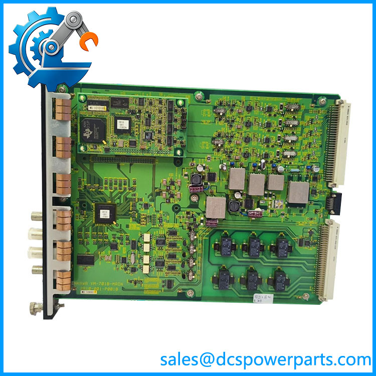
VM-701B/NB1/CS1/TRP/TB1
RMS and peak-to-peak processing
The VM-701B supports multiple rectification methods, including RMS, peak-to-peak, and low-speed peak-to-peak processing for applicable displacement measurements. Shinkawa notes that RMS processing is useful where noise resistance or runout suppression is important, while peak processing is suited to faster response and true peak-to-peak measurement.
The selectable processing method affects what the DCS or historian ultimately sees as the vibration value. A replacement should therefore retain the existing configuration instead of simply loading a nominal default.
Configurable filtering
The module provides field-selectable high-pass and low-pass filters. For RMS processing, the documented four-pole HPF range extends from 2 Hz to 1 kHz, with a four-pole LPF range from 200 Hz to 10 kHz, subject to permitted filter combinations. Ten-pole HPF options are also available in specified ranges.
This is important in machinery monitoring because the filtering determines how much shaft-running-frequency content, structural vibration, low-frequency runout, and higher-frequency noise reaches the alarm calculation.
Four recorder outputs
Each module has four recorder outputs. A measurement from any channel can be assigned to an output channel on the same module, with selectable 1–5 V, 4–20 mA, 0–5 V, or 0–10 V output ranges. Current-mode load is specified up to 600 Ω.
That arrangement allows the VM-701B to feed a DCS, PLC, panel meter, data recorder, or other analog acquisition system without requiring an additional signal-conversion module.
Six independent relay contacts
Six SPDT dry-contact relays provide alarm/status interfaces. Their energization method can be selected as normally energized or normally de-energized, and the contacts are rated at 250 VAC/5 A or 30 VDC/5 A.
The VM-701B’s alarm architecture supports two danger/alert points for vibration monitoring and four high/low alarm points for displacement monitoring. Alarm delay is adjustable from 0 to 99 seconds in 0.1-second increments.
For a protection-related installation, those settings should be recorded before replacing the module. The six relay contacts may be wired directly into annunciation, permissive, interlock, or shutdown logic.
Startup sequence function
Rotating machinery often produces elevated vibration during startup. The VM-701B includes a sequence function intended to prevent excessive startup vibration from immediately producing the normal alarm response. The sequence can block Danger/Alert alarms or switch to another alarm setting multiplied by a configurable factor from 1 to 10.
This is a practical feature, but it introduces one procurement concern: the configured sequence behavior matters. Shinkawa warns that when the sequence multiplication factor is set from 2 to 10, the multiplied alarm setting must remain within the documented limit relative to the maximum monitoring range or the alarm may not output as expected.
Suppression function
A configurable suppression function can suppress a measured vibration value and recorder output when the vibration is below the selected suppression threshold. The documented setup range is 0–5% in 0.1% increments.
This can help prevent low-level noise or probe/runout behavior from creating unnecessary recorder activity. Again, though, it should be treated as part of the machine’s existing configuration rather than a generic factory setting.
/NB1 hazardous-location configuration
The /NB1 suffix specifies a non-incendive configuration with CSA C/US Class I, Division 2, Groups A, B, C and D classification.
This is a real compatibility parameter. A standard VM-701B without the appropriate hazardous-location designation should not automatically be considered an equivalent replacement in a Class I, Division 2 installation.
/CS1 custom monitor configuration
/CS1 identifies a custom monitor-function setup. Shinkawa’s specification explicitly separates this from the base VM-701B model.
That means alarm thresholds, processing selections, output assignments, and other application settings may differ from the default values listed in the specification. A replacement should therefore be configured from the installed system records where possible.
/TRP tropical specification
The /TRP suffix specifies the tropical version. The published environmental specification is 0 to +65°C with 20–95% RH non-condensing, while the hazardous-location construction is specified for 0 to +60°C.
For equipment installed in high-humidity industrial environments, retaining the complete environmental option is preferable to substituting a visually identical standard module.
/TB1 terminal-block package
The /TB1 option is intended for the VM-761B instrument rack. It includes the transducer input terminal-block plugs, recorder-output terminal-block plugs, and contact-output terminal-block plug. Shinkawa specifies Phoenix Contact FRONT-MC series plugs for these connections.
One easily missed detail: the /TB1 package does not include the D-sub plug and hood for the monitor-output connector. If the existing cabinet does not have those parts, they need to be procured separately.
Related Products
- VM-702B — Absolute vibration monitor for VM-7B systems; used for absolute vibration rather than the broader vibration/displacement functions of the VM-701B.
- VM-703B — Tachometer and eccentricity monitor; handles rotational speed and shaft eccentricity rather than four-channel vibration/displacement monitoring.
- VM-704B — Temperature monitor module for thermocouple and RTD measurements.
- VM-706B — Rod-drop monitor for reciprocating machinery applications.
- VM-721B — 18-channel relay module for expanding VM-7B alarm/contact functionality.
- VM-731B — Analysis module for VM-7B monitoring data and waveform/trend processing.
- VM-741B — Local communication and phase-marker module used for phase-marker and synchronized signal functions.
- VM-742B — Upper-level network communication module for the VM-7B system.
- VM-751B / VM-753B / VM-754B — VM-7B power-supply modules covering different input-power arrangements.
- VM-761B — Instrument rack specifically associated with the
/TB1terminal-block configuration of the VM-701B.
Shinkawa’s lifecycle documentation states that the older VM-7 series moved to the VM-7B series, and lists the VM-701 among the discontinued VM-7 monitor products. The manufacturer describes the newer VM-7B products as recommended successors requiring a rack/software-level upgrade rather than a simple one-for-one module substitution.
FAQ
What is the Shinkawa VM-701B/NB1/CS1/TRP/TB1 used for?
It is a four-channel vibration and displacement monitor module for the Shinkawa VM-7B monitoring system. It can process displacement-vibration, velocity-vibration, acceleration-vibration, and displacement signals depending on the connected transducer and configured measurement mode.
Is the VM-701B a PLC or DCS analog input module?
No. It is a dedicated rotating-machinery monitoring instrument. Its six relay outputs, four recorder outputs, filtering, rectification, and alarm-processing functions are designed around machinery-condition monitoring rather than general PLC/DCS I/O.
Can I hot-swap this module?
Do not assume unrestricted hot swapping. Although the VM-701B is a plug-in rack module, removing it can interrupt vibration monitoring and associated alarm contacts. Follow the plant’s machinery-protection maintenance procedure and the applicable Shinkawa VM-7B documentation before removing an energized module.
What does /NB1 mean?
/NB1 specifies the non-incendive configuration with CSA C/US Class I, Division 2, Groups A, B, C and D classification.
What does /CS1 mean?
/CS1 means custom monitor-function setup. The exact installed alarm and processing configuration should therefore be verified rather than relying on the default settings printed in the general specification.
What does /TRP mean?
/TRP identifies the tropical specification. Shinkawa specifies 0–65°C operating temperature and 20–95% RH non-condensing for the general module, with 0–60°C specified for the hazardous-location construction.
What does /TB1 mean?
/TB1 identifies the I/O terminal-block package for the VM-761B instrument rack. It includes two 15-pin transducer-input plugs, two 6-pin recorder-output plugs, and one 18-pin contact-output plug. The D-sub plug and hood for the monitor-output connector are not included.
What sensors can the VM-701B accept?
The documented sensor families include FK/VK displacement probes, CV-series velocity sensors, CA-series acceleration sensors, and several direct-displacement probe configurations. The exact allowable sensor depends on the selected measurement function and configuration.
Does the VM-701B support 4–20 mA signals?
Yes. The specification lists 4–20 mA as a current-signal input option and provides four configurable recorder outputs that can also be set to 4–20 mA. The input impedance for current-signal input is approximately 250 Ω.
Does it support firmware v3.1?
A specific firmware version such as v3.1 should not be assigned to the VM-701B from the model number. Shinkawa does warn that some functions may not be available with older versions and directs users to its infiSYS family improvement information. For a legacy replacement, verify the installed system/software revision rather than assuming firmware compatibility.
What is the standard VM-701B alarm setup?
The published default example uses a 0–100 μm peak-to-peak displacement-vibration range, with 80 μm Danger and 60 μm Alert settings, 3-second alarm delay, auto-reset, and four recorder outputs set to 4–20 mA. Those are default values, not proof of the settings in a /CS1 custom-configured unit.
Is the VM-701B still a current product?
Shinkawa’s lifecycle documentation states that the earlier VM-7 series was moved to the VM-7B series and identifies the older VM-701 as discontinued. The manufacturer’s recommended successor approach is described as a functional upgrade involving rack and software changes, not simply a guaranteed plug-in replacement.
Procurement Note
For Shinkawa VM-701B/NB1/CS1/TRP/TB1, purchase against the complete suffix, not just “VM-701B.”
The four suffixes each carry engineering significance:
/NB1 → Class I Division 2 non-incendive configuration
/CS1 → custom monitor-function setup
/TRP → tropical specification
/TB1 → VM-761B rack terminal-block package
Before approving a replacement, verify:
Exact model → installed VM-761B rack → sensor type for each channel → measurement mode → HPF/LPF settings → rectification method → alarm setpoints → relay energization → recorder output ranges → hazardous-location requirement.
The /CS1 suffix deserves particular attention. A replacement can have the correct hardware and still behave differently if the custom monitoring parameters are not restored. The default 80 μm Danger / 60 μm Alert example should not be copied into the plant configuration without checking the original settings.
Also verify the terminal accessories. /TB1 includes the rack-side terminal plugs but does not include the D-sub plug and hood for the monitor-output connector. That small omission can delay a cabinet repair if the existing connector hardware has been damaged or discarded.
For critical turbine, compressor, pump, or other rotating-equipment service, the procurement package should include:
VM-701B/NB1/CS1/TRP/TB1 → nameplate photograph → board/revision identification → rack model → sensor list → configuration backup → alarm settings → functional test evidence.
That is the level of identification I would require before treating this module as a direct maintenance spare.