Description
PdMA MTAP2 PCB-00322-REVD
Product Introduction
Motor testing becomes a very different maintenance task when the technician has to open an energized MCC or switchgear enclosure just to reach the required measurement points. The PdMA MTAP2 PCB-00322-REVD addresses that problem by providing a dedicated Motor Test Access Port for connecting compatible motor-analysis equipment from outside the enclosure. Available documentation identifies the unit as the PCB-00322 Rev D hardware used in the MTAP2 system.
The important distinction is that this is not a conventional PLC I/O board or motor-control output module. It is part of a motor diagnostic access system, providing the interface between the motor circuit and compatible PdMA test equipment. For maintenance groups supporting existing MTAP2 installations, the exact PCB revision matters; do not substitute a visually similar board without checking the enclosure, connector arrangement, cable assembly, and tester compatibility.
Key Technical Specifications
| Parameter | Specification |
|---|---|
| Product Model | MTAP2 PCB-00322-REVD |
| Manufacturer / Brand | PdMA Corporation |
| Product Family | MTAP2 Motor Test Access Port |
| PCB Number | PCB-00322 |
| Hardware Revision | Rev D |
| Product Type | Motor Test Access Port / diagnostic interface PCB |
| Primary Function | External access to motor electrical test signals |
| Application | Motor condition testing in MCC / switchgear environments |
| Compatible Testers | PdMA M-Series EMAX and MCEMAX portable testers |
| Installation | access-port assembly / motor-control enclosure |
| Safety Concept | Closed-door motor testing interface |
| Standards Information | Available product records state UL/CSA-recognized components and CSA listing to UL508 and CSA 22.2 No. 14 for the module; verify certification markings on the actual assembly. |
| Revision | REV D |
The documentation available through secondary equipment records states that the access port is designed for testing energized AC motors and generators without opening the MCC or switchgear door. Those records also identify compatibility with PdMA M-Series EMAX and MCEMAX portable testers and describe a test-port voltage below 50 V at the user connection point.
Procurement note: I would not publish the conflicting values found on several reseller pages for input voltage, CT rating, USB connectivity, dimensions, or operating temperature as definitive PCB-00322-REVD specifications. Those listings disagree materially with one another and appear to mix assembly-level information with unrelated technical data.

MTAP2 PCB-00322-REVD
Application Scenarios & Pain Points
The exists because conventional motor testing can create an unnecessary maintenance exposure: technicians may need access to motor-circuit signals while the associated equipment remains energized.
Typical applications include:
- Motor control center testing — Provides an external connection point for compatible motor diagnostic equipment without routinely opening the MCC enclosure.
- Predictive motor maintenance — Supports electrical measurements used by PdMA motor-analysis equipment for assessing motor condition.
- Generator testing — Available documentation identifies the platform for energized AC motor and generator testing.
- Maintenance standardization — A permanently installed access point can reduce repeated temporary probing and connection work during scheduled testing.
- High-voltage cabinet maintenance — The system is intended to move the tester connection point away from direct exposure to the internal motor-control circuitry.
From a field-engineering standpoint, the real value is not the PCB by itself. It is the installed test-access architecture. If the cabinet already has an assembly, replacing the correct PCB can be considerably less disruptive than redesigning the motor-testing interface.
Related Products
- PdMA Motor Test Access Port — The complete access-port assembly in which -REVD is used.
- PdMA M-Series EMAX — Portable motor-analysis equipment documented for use with .
- PdMA MCEMAX — Another compatible PdMA portable tester identified in documentation.
- earlier revisions — Earlier hardware revisions may appear in existing installations, but revision-to-revision interchangeability should be confirmed rather than assumed.
- cable assembly — The cable connecting the access port to the external test equipment is a system-level compatibility item and should be checked when replacing an assembly.
- Motor current-transformer components — CT-related hardware is part of some configurations; confirm the actual installed assembly before ordering separate CTs.
- MCC motor feeder hardware — The access port works in conjunction with the motor feeder’s existing electrical circuit rather than replacing the starter, drive, breaker, or overload system.
Engineer’s Guide: Field Pitfalls to Avoid
1. Do not mistake -REVD for a PLC control board
The PCB is part of a motor diagnostic access system. It does not replace a PLC output module, VFD control card, motor starter, or protective relay.
Before ordering, identify whether the failed item is the PCB itself, the complete assembly, the external cable, or another cabinet component.
2. Verify the complete revision marking
The suffix REVD is meaningful.
If the installed board is marked , record the complete marking, connector layout, cable connections, and any additional assembly numbers before removing it. Do not accept “ equivalent” as sufficient identification.
3. Do not assume every electrical specification found online is valid
Several reseller pages publish dramatically different values for temperature, CT rating, input voltage, dimensions, and interfaces. Those specifications are not consistent enough to treat as authoritative.
For a safety-related measurement interface, the correct approach is simple: use the original PdMA documentation, cabinet drawings, nameplate, and installed configuration as the final reference.
4. Check tester and cable compatibility
The is designed around a specific diagnostic workflow. The available documentation identifies PdMA M-Series EMAX and MCEMAX testers as compatible equipment.
A replacement PCB that fits mechanically but does not match the installed cable or tester configuration is not a successful replacement.
5. Treat the port as part of a safety system
The purpose of the is to reduce exposure during motor testing. That does not mean technicians should bypass cabinet safety procedures or assume that an external test port makes every test condition safe.
Verify the actual installed protection, test-port condition, enclosure labeling, grounding, and applicable site electrical-safety procedures before testing.
6. Inspect the complete assembly, not only the PCB
For used inventory, check:
- PCB revision marking
- Terminal condition
- Connector damage
- Fuse condition where applicable
- Evidence of overheating
- Contamination or moisture
- Cable insulation
- Enclosure/interface condition
- Any signs of previous electrical fault
A visually clean PCB does not prove that the complete assembly is electrically serviceable.
7. Do not confuse the PCB with the complete assembly
Some supplie” and “ Motor Test Access Port” almost interchangeably. Procurement should establish exactly what is included: PCB only, complete access-port assembly, cable, CTs, enclosure hardware, or a tested assembly.
That distinction can materially change both installation work and acceptance testing.
FAQ
What ?
It is a Rev D PCB associated with the PdMA Motor Test Access Port. The is used to provide an external connection point for motor diagnostic testing in MCC and switchgear environments.
a PLC or DCS module?
No. It is a motor diagnostic/test-access component, not a conventional PLC, DCS, or remote-I/O module. Its function is associated with motor electrical measurement and connection to compatible diagnostic equipment.
What equipment is compatible with the ?
Available documentation identifies PdMA M-Series EMAX and MCEMAX portable testers as compatible with . A dedicated cable is used to connect the access port to the tester.
be used as a replacement for an ear00322 revision?
It may be possible within the family, but I would not approve the substitution solely from the PCB number. Confirm the cabinet assembly, connector arrangement, cable, tester, and revision documentation before installation.
Does the allow testing without opening the MCC door?
That is the intended operating concept. Available documentation states that allows facilities to test energized AC motors and generators without opening the MCC or switchgear doors, with the user-facing test port designed to keep the connection point at a substantially reduced voltage.
What should I request when buying a replacement PCB?
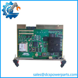
Ask the supplier for a clear photograph showing , the complete board, connectors, and any additional PdMA identification labels. If the application is safety-critical, request confirmation of whether the quotation covers the PCB alone or the complete assembly, and require functional testing against the intended tester/cable configuration.
What is the biggest procurement risk with this part?
The biggest risk is buying a part described simply as without confirming the exact PCB revision and assembly scope. There are several conflicting third-party technical descriptions online, so the exact nameplate and installed configuration should take precedence over generic reseller specifications.