Description
Product Overview
1MRK002122-ABr13 is a recent-build revision of the short-range optical line data communication module that ABB fits into Relion 670 terminals under the catalogue entry “Optical short range LDCM” and the factory marking 670LDCM02 SHORT. The -AB suffix fixes the optical interface to multimode glass at 820 nm; the r13 marking identifies the build level, which changes sourcing and process maturity rather than signal behaviour. The board is a plug-in card for a remote-communication position in a RED670, REG670, REL670, RET670 or REC670 chassis.
Its role is often described as “the protection channel”, which understates where it sits. In a real scheme the module is the demarcation point between the IED and whatever carries the signal onward: in one station a duplex multimode pair goes directly to the far end; in another it terminates on an external optical-to-G.703 converter feeding a PDH or SDH multiplexer, with the telecom network beyond. Between the LDCM and that converter, C37.94 framing is used regardless — the module does not know, and does not need to know, whether dark fiber or a leased network lies past its own connector.
What it carries is a telegram every 5 ms: three-phase current samples, the time reference aligning both terminals, trip and block indications, alarms and eight binary signals for transfer trip or interlocking. On the direct-fiber path the board’s own 13 dB budget governs reach — about 3 km on 62.5/125 µm, 2 km on 50/125 µm, at −17 dBm launch and −30 dBm sensitivity. On the multiplexed path the multimode hop to the converter is normally kept within 3 km, and the distance question moves into the telecom domain where a different set of engineering rules applies.
Technical Specifications
| Parameter | Value |
|---|---|
| Model | 1MRK002122-ABr13 |
| Hardware revision | r13, functionally identical to earlier builds of the type |
| Manufacturer | ABB, Sweden |
| Product type | Optical short range line data communication module, IED plug-in board |
| Optical connector | ST duplex, transmit and receive pair |
| Fiber | Graded-index multimode 62.5/125 µm standard; 50/125 µm supported |
| Wavelength | 820 nm peak emission, 865 nm nominal, 792 nm minimum |
| Optical budget | 13 dB on 62.5/125 µm, 9 dB on 50/125 µm |
| Direct-fiber reach | Approximately 3 km and 2 km respectively, by link calculation |
| Hop to external converter | Multimode fiber, normally within 3 km, C37.94 maintained to the converter |
| Launch and sensitivity | −17 dBm minimum output on 62.5/125 µm; −30 dBm receiver sensitivity |
| Protocol and framing | IEEE C37.94 synchronous, HDLC |
| Data rate | 64 kbit/s default, 2 Mbit/s mode selectable |
| Telegram payload | Three-phase currents every 5 ms, time reference, trip/block/alarm, eight binary signals |
| Channels per terminal | Up to four remote communication interfaces |
| Power | From the IED backplane, no independent supply |
| Slot positions | P30:5, P30:6, P31:3, P32:2, P32:3 by chassis variant |
| Compliance | IEC 60255-26 EMC, IEC 60255-1 and IEC 60255-27 for the parent IED |
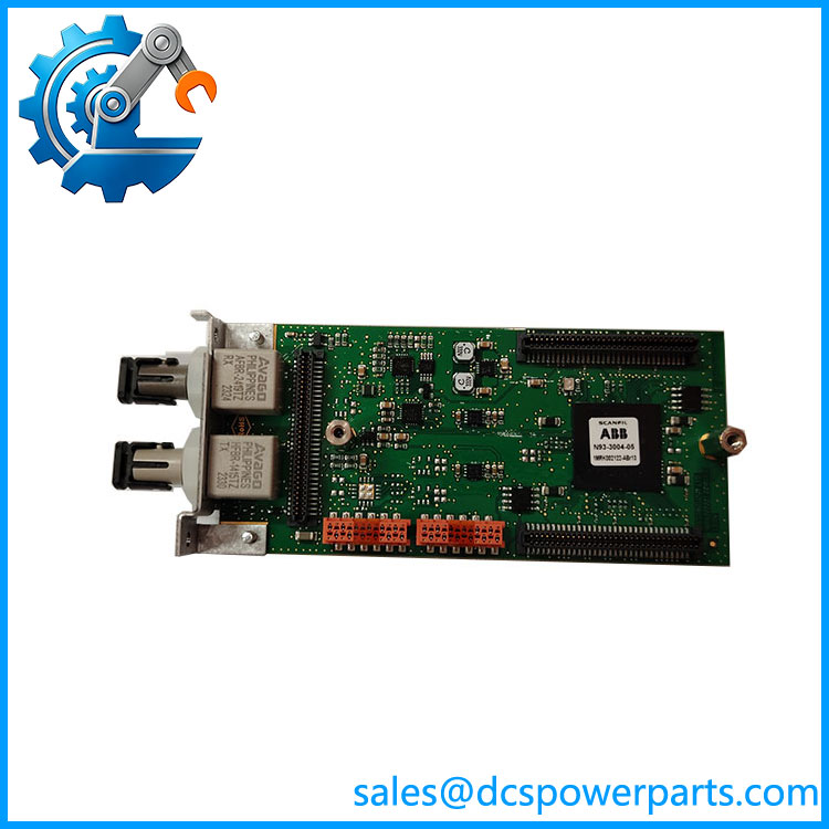
1MRK002122-ABr13
Key Features and Advantages
A demarcation point that keeps two engineering worlds apart
Because the module always presents the same C37.94 interface, the protection engineer and the telecom engineer can each work to their own rules. The protection side owns the converter-facing hop, the framing and the clock relationship; the telecom side owns the multiplexer, the channel allocation and the SDH protection switching. 1MRK002122-ABr13 makes that boundary explicit instead of leaving it as an assumption between two departments.
The 3 km rule to the converter
When an external optical-to-galvanic converter is used, the connection from the LDCM is multimode fiber and is normally kept within 3 km — a figure that follows directly from the short-range budget rather than from a vendor preference. Colocating the converter in the same room as the terminal removes that hop entirely and leaves only the telecom link to be engineered, which is the cleanest arrangement in a station with an existing transmission room.
Payload and timing unchanged across either route
Whether the channel runs on dark fiber or through a multiplexer, the same telegram leaves the board every 5 ms and the same clock relationship has to be maintained; one end generates timing and the other derives it. That constancy is what allows a scheme to be migrated from direct fiber to a leased network — or the reverse — without touching the differential settings, only the channel configuration.
Diagnostics that sit at the handover point
Launch power, received level and supervision counters are all observable from the terminal, which makes the LDCM the natural first place to look when a channel misbehaves. A fault downstream in the telecom network and a dirty ST ferrule in the station present very differently at this point, and separating them saves the escalation that otherwise goes to the wrong team.
Applications
Transmission feeders where only part of the route is owned fiber are the classic case: a utility with an SDH network between two substations can run differential protection across it by terminating 1MRK002122-ABr13 on converters at each end, keeping C37.94 to the modem and G.703 into the multiplexer. The same arrangement suits operators who hold a leased 64 kbit/s circuit rather than dark fiber, and it lets the protection scheme survive a later change of transmission technology.
Direct-fiber schemes remain the simpler option wherever a pair of multimode strands already links two buildings — a station compound split by a road, a hydro plant and its switchyard, adjacent substations on a metro cable route. In those cases the board’s own budget carries the whole distance and no converter appears in the design.
Industrial sites with a private telecom room use the multiplexed arrangement across a large complex where the cable route is long but a PDH link already exists — a refinery, a port, an integrated steel works. Schemes carrying only binary signals, such as transfer trip or busbar-to-line interlocking, use the same board and take the same route decision, and test departments prove the pair back to back over a short patch cord before commissioning.
Related Products
1MRK002311-AA — medium range LDCM, single-mode 9/125 µm at 1310 nm with FC/PC connectors and 22 dB budget, used where the direct route exceeds multimode limits. 1MRK002311-BA — long range LDCM at 1550 nm, 26 dB budget, for the 110 to 130 km band. 1MRK005500-AA — Ethernet SFP module, optical LC connector, for IEC 61850 station bus traffic. 1MRK005500-BA — Ethernet SFP module, RJ45 connector, the copper station-bus variant. 1MRK002266-EA — optical Ethernet module for station communication on the same platform. 1MRK001608-AB / 1MRK001608-BB / 1MRK001608-CB — serial modules for SPA, LON, DNP and IEC 60870-5-103 in plastic, plastic-glass and glass versions. 1MRK002309-AA — galvanic RS485 module for short copper links within a station. 1MRK007002-AA — GPS time module, where the differential function is clocked from a global reference rather than from the channel. 1MRK002282-AB — IRIG-B synchronization module, the alternative external time base. RED670 / REL670 / REG670 — terminals hosting 1MRK002122-ABr13 in line differential, distance and generator protection.
Installation and Maintenance
Before installation: decide the architecture before the hardware. Confirm whether the channel will run on direct fiber or through converters and a multiplexer, because that decision fixes the budget calculation, the patch-cord lengths and the room layout. For direct fiber, survey with an optical time-domain reflectometer and compare the measured loss with the 13 dB figure on 1MRK002122-ABr13; for the converter path, keep the multimode hop within 3 km and place the converter as close to the terminal as the transmission room allows. Verify that the free position is a remote-communication slot at P30:5, P30:6, P31:3, P32:2 or P32:3, isolate the IED, then fit the module.
Maintenance practice: clean ST ferrules before each mating, and record launch power and received level at both ends at commissioning — on a multiplexed route these readings are the only local evidence that the station hop is intact. Re-measure annually and after any work in the transmission room; a decline confined to one end points at connectors there, while a change common to both ends suggests the telecom path. After a board change, restore the channel configuration, confirm master and slave clock roles, run a loop-back test and read the supervision counters. Keep spare 1MRK002122-ABr13 units capped and revision-labeled, since a late build is the one most likely to remain obtainable for a mature terminal.
Warranty and Quality
1MRK002122-ABr13 is delivered as a plug-in module with the revision level shown on the label and repeated in the packing documentation, so the position it fills is documented from receipt. Each unit passes a fiber loop-back verification covering launch power, received level, frame lock and channel status, and the measurement sheet accompanies the shipment. A 12-month warranty applies under standard substation-automation practice, covering repair or replacement for quality-related failures. Where a scheme uses two or three modules, sets are checked for revision consistency before dispatch. Support covers slot mapping, clock role configuration, budget review from survey data, the low or high power decision, and the choice between direct fiber and a converter-and-multiplexer arrangement.