Description
MTL5053 IS Isolator / Power Supply – 31.25 kbit/s H1 Fieldbus
Product Overview
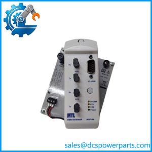
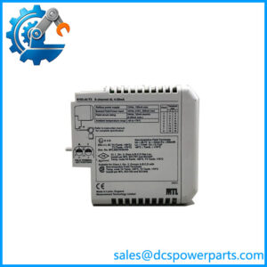
The MTL5053 is an MTL5000 Series intrinsically safe fieldbus isolator and power supply designed for extending 31.25 kbit/s H1 Foundation Fieldbus networks into hazardous areas. Rather than functioning as a PLC or DCS I/O channel, the unit sits between the safe-area host-side fieldbus and field devices installed in a hazardous location. It supplies power to field devices through the fieldbus signal conductors while maintaining the electrical separation required between the safe and hazardous sides. Eaton’s documentation identifies the device as an IS power supply conforming to the Fieldbus Foundation Type 133 specification.
The MTL5053 provides a hazardous-area fieldbus supply of 18.4 V ±2% with 105 Ω ±3% DC impedance and a maximum output current of 80 mA. It is compatible with 31.25 kbit/s fieldbus communication and is intended for installations where field instruments require power and digital communication over the same two-wire fieldbus circuit. The safe-area supply input is 20–35 VDC, while the module provides 250 VAC isolation between the safe-area and hazardous-area circuits and the power supply.
For fieldbus commissioning and maintenance, the MTL5053 also provides terminals for an optional hand-held communicator connection, and an internal fieldbus terminator can be enabled when the safe-area bus arrangement requires it. Terminal assignments separate the hazardous-area fieldbus, optional HHC connection, safe-area fieldbus, and DC supply connections. This makes the module particularly relevant to legacy process-control installations where intrinsic-safety requirements must be maintained without replacing the existing H1 fieldbus architecture.
Product Introduction
The MTL5053 is installed in the safe area and interfaces the host-side fieldbus with an intrinsically safe fieldbus segment serving hazardous-area instruments. Typical applications include process transmitters, valve positioners, and other Foundation Fieldbus H1 devices where both communication and field-device power are carried on the same field wiring.
The module is designed around the electrical characteristics of conventional 31.25 kbit/s fieldbus systems. Its 18.4 V nominal hazardous-area supply and 80 mA maximum current capability must be considered together with the total field-device load, cable characteristics, voltage drop, and applicable intrinsic-safety entity parameters.
Main Features and Advantages
H1 Fieldbus Power and Communication
The primary purpose of the MTL5053 is to provide both power and communication for hazardous-area H1 fieldbus devices. The unit supports the 31.25 kbit/s fieldbus physical layer and is intended for systems using the conventional two-wire fieldbus architecture. This allows field instruments to remain connected through a single fieldbus pair rather than requiring separate power and communication wiring.
Intrinsically Safe Hazardous-Area Interface
The hazardous-area output is specified at 18.4 V ±2%, with 105 Ω ±3% DC impedance and an 80 mA maximum current. The manufacturer documentation identifies suitable applications extending into Zone 0, IIC, T4–T6 hazardous areas when the connected equipment and installation are appropriately certified. The exact permitted installation category depends on the complete intrinsic-safety system, not simply the presence of an MTL5053.
Electrical Isolation
The MTL5053 provides 250 VAC isolation between the safe-area circuit, hazardous-area circuit, and power supply. This separation is important when the fieldbus segment crosses the boundary between ordinary control-system equipment and hazardous process areas.
Integrated Termination Capability
A practical feature is the selectable internal fieldbus terminator. The manufacturer specifies that the terminator can be enabled using a switch on the module when the safe-area bus arrangement requires termination at that location. Proper fieldbus termination remains important because incorrect termination can cause communication instability that may otherwise be mistaken for a device or controller fault.
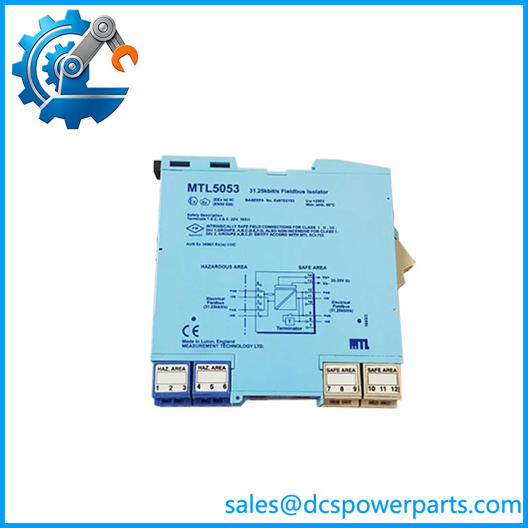
MTL5053
Hand-Held Communicator Connection
Terminals 4 and 5 are provided for an optional hand-held communicator connection. This can simplify field commissioning and maintenance without changing the primary host-side fieldbus architecture.
DIN-Rail Installation
The MTL5000 mechanical design supports DIN-rail installation. Eaton recommends mounting the MTL5053 horizontally on a DIN rail attached to a vertical surface, with 10 mm spacing between adjacent units to assist heat dissipation. If the module is installed in a non-optimum orientation, the specified maximum operating temperature is reduced to 45°C.
Procurement and Replacement Considerations
The MTL5053 is an established MTL5000-series product, so replacement purchasing should focus on the exact MTL5053 designation, hazardous-area certification requirements, fieldbus architecture, and installation arrangement rather than assuming that any H1 power supply is interchangeable.
The manufacturer’s documentation currently lists several certification records for MTL5053, with some older approvals marked obsolete or terminated and other certification records shown as current. Certification status should therefore be checked against the intended installation jurisdiction and the exact product marking before shipment to a hazardous-area project.
For replacement work, verify the existing fieldbus load before selecting the unit. The 80 mA maximum hazardous-area output is a system constraint; the number of connected instruments cannot be determined from device count alone because instrument consumption, cable resistance, voltage drop, and intrinsic-safety limitations all affect the usable segment capacity.
Key Technical Specifications
| Parameter | Specification |
|---|---|
| Manufacturer | MTL / Eaton |
| Model | MTL5053 |
| Series | MTL5000 |
| Product Type | IS Fieldbus Isolator / Power Supply |
| Fieldbus Type | 31.25 kbit/s H1 Fieldbus |
| Application | Hazardous-area Foundation Fieldbus |
| Safe-Area Supply | 20–35 VDC |
| Hazardous-Area Supply | 18.4 V ±2% |
| Maximum Hazardous-Area Current | 80 mA |
| Hazardous-Area DC Impedance | 105 Ω ±3% |
| Isolation | 250 VAC between safe-area, hazardous-area circuits and power supply |
| Safety Description, Terminals 1–2 | 22 V, 102 Ω, 216 mA |
| Optional HHC Connection | Terminals 4 and 5 |
| Hazardous-Area Fieldbus | Terminals 1 and 2 |
| Safe-Area Fieldbus | Terminals 8/11 and 9/12 |
| DC Supply | Terminals 13 and 14 |
| Power Indicator | Green LED |
| Internal Terminator | Selectable |
| Mounting | DIN rail |
| Recommended Installation Spacing | 10 mm between adjacent modules |
| Maximum Temperature in Non-Optimum Orientation | 45°C |
| Fieldbus Standard Compatibility | Foundation Fieldbus 31.25 kbit/s / IEC 61158-2 / ISA-S50.02 |
| Hazardous-Area Capability | Zone 0, IIC, T4–T6 when suitably certified |
Specifications above are taken primarily from the MTL5053 manufacturer datasheet.
Terminal Configuration
| Terminal | Function |
|---|---|
| 1 | Hazardous-area fieldbus connection – |
| 2 | Hazardous-area fieldbus connection + |
| 4 | Optional HHC connection – |
| 5 | Optional HHC connection + |
| 8 & 11 | Safe-area fieldbus connection – |
| 9 & 12 | Safe-area fieldbus connection + |
| 13 | DC supply – |
| 14 | DC supply + |
| 3, 6, 7, 10 | Cable-screen termination points; no internal electrical connection |
The manufacturer’s datasheet specifically notes that terminals 3, 6, 7, and 10 are provided to assist cable-screen termination but have no internal connection and are not internally earthed.
Related Products
- MTL5043 – Repeater Power Supply
- MTL5044 – Repeater Power Supply
- MTL5040 – Loop Isolator
- MTL5045 – Isolating Driver
- MTL5046 – Isolating Driver
- MTL5081 – Millivolt/Thermocouple Isolator
- MTL5082 – Resistance Isolator
- MTL5344 – Repeater Power Supply
- FBT1-IS – Fieldbus Terminator
These products belong to the broader MTL intrinsic-safety and field-interface product range; they should not be treated as direct functional substitutes for the MTL5053 without checking the application.
Frequently Asked Questions
What is the MTL5053 used for?
The MTL5053 is used to extend 31.25 kbit/s H1 Foundation Fieldbus networks into hazardous areas while providing intrinsically safe fieldbus power and maintaining communication with the safe-area host system.
Is the MTL5053 an I/O module?
No. It is an intrinsically safe fieldbus isolator/power supply. It does not provide conventional PLC/DCS analog or digital I/O channels.
What supply voltage does the MTL5053 require?
The specified safe-area supply input is 20–35 VDC.
How much current can the hazardous-area fieldbus supply provide?
The hazardous-area fieldbus supply is rated for a maximum of 80 mA, with a nominal output of 18.4 V ±2%.
Does the MTL5053 support 31.25 kbit/s Fieldbus?
Yes. It was specifically developed for 31.25 kbit/s H1 fieldbus networks and complies with the applicable fieldbus physical-layer requirements identified in the manufacturer documentation.
Does it have an integrated fieldbus terminator?
Yes. An internal terminator can be selected by the module switch when required by the fieldbus topology.
Is MTL5053 suitable for hazardous-area applications?
It is designed as an intrinsic-safety fieldbus interface, with manufacturer documentation identifying use for suitably certified equipment in hazardous locations. The complete installation must still satisfy the applicable hazardous-area certification and entity-parameter requirements.
What should be checked before replacing an MTL5053?
Confirm the exact model marking, fieldbus segment load, supply voltage, termination arrangement, hazardous-area certification requirements, cable parameters, and connected field-device entity parameters. These checks are more important than simply matching the physical appearance of the replacement unit.