Description
Product Overview
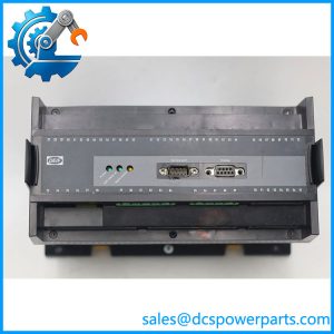
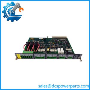
PSM-1 is the only power module in a DELOMATIC 3 generator unit, and one is fitted in every DGU. It takes the plant’s or vessel’s 24 V DC at its “SUPP.” terminals, converts it into a switch-mode backplane supply of ±5 V, ±12 V and ±15 V DC, and feeds every other board in the rack — the CM-2 control module, the IPM-1 inputs, the OPM-1 relay outputs, the AOM-1 analogue outputs, the SCM-1 and SCM-2 measuring boards, the protection modules, all of it.
The function that is usually overlooked is isolation. PSM-1 provides galvanic separation between the power source connected at its supply terminals and the DELOMATIC system behind it, tested at 1.0 kV, 50 Hz for one minute to GL, LR and DNV practice. That makes the module the reference boundary of the whole cabinet: the battery side carries the ship’s or plant’s grounding arrangement, and everything on the backplane side sits behind an insulated barrier. Cabinets get wired wrongly when this is not understood — Earth on the supply side and Earth on a field-device side, both bonded to the same rack, silently defeat the isolation the module was installed to provide.
The electrical contract it expects is narrow and specific. Nominal 24 V DC, +30 % / −25 %, ripple included, and an absolute rule that the supply must never exceed 32 V DC regardless of circumstances. On a vessel under equalising charge, or on a plant with a 24 V charger that lifts to 29–30 V, that ceiling is not academic; it is a check to be done against the charger’s set-points rather than against the battery’s nominal label. The module is internally protected against surges and transients, and the external circuit is to be protected with a slow-blow fuse of no more than 6 A.
Its own two LEDs describe the supply rather than the module. Green POWER OK means the PSM is able to obtain correct and sufficient power for the rack. Red LOW POWER means it cannot supply the modules — triggered when the external supply falls below roughly 12 V DC. Between those states sits a deliberate and often-misread behaviour: the DELOMATIC system stays disabled until the external supply recovers above 18 V DC, that is 24 V minus 25 %. After a deep battery sag or a generator blackout, the rack therefore does not come back the instant voltage begins to rise; it waits for 18 V. Operators read that as a dead controller, and the actual answer is a supply that has not yet recovered. Below about 4 V DC the LOW POWER LED fades out entirely, which is the module telling you there is nothing to work with rather than reporting a fault.
One line in DEIF’s data sheet deserves to be treated as an instruction rather than a note: short-term loss of power must be avoided, as it may damage the module. The recommended remedy is a capacitor of at least 1000 µF, 30 V DC, across the supply terminals at the PSM-1 when the 24 V source is unstable or under-dimensioned, fitted specifically to prevent unintended warm restarts of the DELOMATIC system. A cabinet whose 24 V rail dips when a contactor pulls in, or whose battery is switched between sources, is exactly the case that damages this board repeatedly and is then blamed on “unreliable electronics”.
Physically, PSM-1 is the widest board in the rack at 8 TE, 40.7 mm across — wider than the 6 TE signal modules — and weighs 0.45 kg. It draws 10 W typical and 15 W maximum for itself, on top of whatever the fitted modules consume, so the rack’s total demand depends on its configuration and cannot be quoted without the module list. Wiring is 2.5 mm² at the screw terminals, the rack is IP20 with cover plates on unused slots, operation is rated to -25 °C with HSE climate class, and the system carries CE marking and type approval from LR, GL, DNV, ABS, BV, RINA and CNK.
Worth stating plainly because it is widely misunderstood: there is one PSM-1 per DGU and no documented redundancy for it. It is the rack’s single point of power, which is why the quality of the 24 V feed — not the module — is the thing to engineer.
DEIF has placed DM-3 at end of life with no direct replacement, so PSM-1 survives as an installed-base spare and as the component whose failure mode most often looks like something else.
Technical Specifications
| Parameter | Value |
|---|---|
| Model | |
| Manufacturer | DEIF A/S, Denmark |
| Product type | Switch-mode power supply module for the DELOMATIC 3 DGU rack |
| Function in system | Backplane supply for all modules in the DGU; one module per DGU |
| Galvanic separation | Between the supply source at the SUPP terminals and the DELOMATIC system; 1.0 kV, 50 Hz, 1 minute to GL / LR / DNV practice |
| Input supply | Nominal 24 V DC, +30 % / −25 %, including peak-to-peak ripple |
| Absolute maximum | Supply must never exceed 32 V DC |
| External protection | Slow-blow fuse, maximum 6 A |
| Backplane outputs | ±5 V DC, ±12 V DC, ±15 V DC, held constant against total backplane consumption within the supply limits |
| Own power consumption | 10 W typical, 15 W maximum, excluding the modules fed from the backplane |
| Indication | Green POWER OK: sufficient supply for the rack; red LOW POWER: supply below approx 12 V DC, system disabled until above 18 V DC |
| Terminals | Screw terminals, 2.5 mm² single or multi-stranded |
| Dimensions / weight | 40.7 mm wide (8 TE); 0.45 kg |
| Environment / protection | Nominal -10 to +55 °C, operational -25 to +70 °C, storage -40 to +70 °C; climate class HSE per DIN 40040; IP20 in rack |
| Approvals | CE marking; system type approval by LR, GL, DNV, ABS, BV, RINA and CNK |
| Lifecycle status | DM-3 platform at end of life at DEIF; no direct replacement |
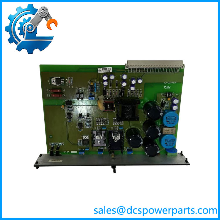
DEIF PSM-1
Key Features and Advantages
Isolation as a design function, not a by-product: places a 1.0 kV-tested galvanic barrier between the battery side and the rack. That protects the control electronics from the transients a ship’s or plant’s DC system carries, and it lets the cabinet’s earthing be designed deliberately rather than incidentally — provided nobody bonds both sides to the same rack afterwards.
A supply contract you can check with a meter: 24 V DC nominal, +30 % / −25 %, 32 V absolute, 6 A slow-blow fuse. Three numbers that turn “the power is fine” into a measurement, and that catch the two real-world cases — an equalising charger lifting past 32 V, and a rail that sags below the disable threshold every time a large contactor closes.
LEDs that report the supply, not the board: POWER OK for a healthy rail, LOW POWER below roughly 12 V, and a system that stays disabled until 18 V. The 12-to-18 V band is hysteresis, and recognising it explains the most common false diagnosis on this platform — a rack that looks dead after a blackout but is merely waiting for the battery to recover.
Damage prevented rather than repaired: DEIF’s own warning that short power interruptions may damage the module, paired with the 1000 µF / 30 V capacitor recommendation, is the cheapest reliability improvement available on an ageing DM-3 cabinet. A bulk capacitor costs a few dollars; a repeated warm-restart cycle costs the board.
Wide input window, narrow output: the switch mode holds ±5 V, ±12 V and ±15 V constant across the full input range and against varying backplane load, so a board added to the rack does not shift the rails the existing modules are calibrated against.
Physically accommodating of its job: 8 TE of rack width gives the converter the space its thermal design needs, and 10 W typical of self-consumption leaves the thermal budget of a closed switchboard room workable at -25 to +70 °C operational.
One supply, honestly single: no pretence of redundancy, no dual-feed marketing language — which is a useful clarity. The engineering effort goes where it belongs, into the 24 V source, its charging profile, its fuse and its bulk capacitance.
Marine-grade approvals at system level: 1.0 kV dielectric test to classification-society practice, UL94-V0 plastics, HSE climate class and type approval from LR, GL, DNV, ABS, BV, RINA and CNK — the basis on which a replacement board can be accepted in a certified switchboard.
A repairable single point: on a platform with no successor product, being able to fit a correct is what keeps a generator unit from being written off over a power supply.
Applications
Ship DC systems feeding generator control: 24 V battery banks with charger and distribution in a switchboard room, where isolates the DELOMATIC rack from the vessel’s DC system and where the charger’s equalising voltage has to be checked against the 32 V ceiling rather than assumed.
Land-based multi-genset plants and standby stations: 24 V control supplies derived from a rectifier or a battery, feeding one DGU per machine. In these cabinets the bulk capacitor recommendation earns its keep, because the 24 V rail is shared with contactor coils and interposing relays whose operation causes exactly the dips the module dislikes.
CHP and industrial captive power: plants where the control supply also feeds auxiliary DC loads, and where the rack’s own consumption — 10 to 15 W from the PSM plus the fitted boards — has to fit a supply sized years earlier for a different configuration.
Isolated grids, ports, mines and remote sites: installations where the 24 V source is a battery charged by a small charger, with no large grid behind it, and where a supply sag during a generator start is both normal and damaging.
Marine auxiliary and offshore switchboards: certified panels where the replacement board must carry the same type approval basis as the original, and where the isolation between the vessel’s DC system and the control electronics is part of the approved arrangement.
Life extension of ageing DGUs: the practical case behind current orders — a rack that restarts spontaneously, or one that stays dark after a blackout, where the fault is a 24 V rail or a fatigued bulk capacitor and the module itself is the innocent party until proven otherwise.
Related Products
CM-2 — control module; one per DGU, supplied from the backplane and holding the application program. IPM-1 — 16-channel universal input module; backplane-fed, no independent supply terminals of its own. OPM-1 — 16-channel relay output module; backplane-fed, driving the DGU’s command outputs. AOM-1 — 8-channel analogue output module; provides the analogue references for governors and AVRs. SCM-1 — synchronising and measuring module; requires its own supply at terminals 27–28 for speed-governor control in switchboard mode, additional to the backplane supply. SCM-2 — synchronising and measuring module for shaft generators and busbar tie breakers. CRM-1 — current protection relay module; when used for internal short-circuit protection it requires its own supply at terminals 13–14. PRM-1 — protective relay module for mains voltage, frequency and negative-sequence conditions. CP-1 — control panel; separately supplied, up to three per DGU. DGU rack — 84 TE or 60 TE backplane assembly in which the 8 TE occupies a slot and feeds all the others.
Installation and Maintenance
Before installation: measure the 24 V source rather than reading its label — confirm the steady-state range falls inside +30 % / −25 % of 24 V, that no operating condition lifts it above the 32 V DC ceiling, and that ripple is within the stated allowance. Check the charger’s equalising set-point explicitly if the supply is a battery, fit a slow-blow fuse of no more than 6 A in the supply circuit, and verify the rack’s total consumption against what the source can deliver. Where the supply is unstable or under-dimensioned, fit a capacitor of at least 1000 µF and at least 30 V DC across the supply terminals at the module, as DEIF recommends to prevent unintended warm restarts. Confirm the board’s 8 TE slot and backplane connector, and check that the supply-side earth and the field-side earth do not end up bonded together on the rack once wiring is complete.
Commissioning: power up and read the two LEDs — POWER OK steady green means the rack has what it needs; LOW POWER red means the input is below roughly 12 V and the system will stay disabled until it reaches 18 V. Prove the behaviour deliberately: pull the supply down and confirm the rack disables and recovers as described, because operators who have not seen it will report the next genuine sag as a controller failure. Verify that every board in the rack is recognised — the CM-2‘s I/O OK indication is the test — and confirm the separately supplied functions, such as SCM-1 speed-governor control and CRM-1 short-circuit protection, are fed at their own terminals, since the backplane supply alone does not enable them.
Maintenance practice: treat spontaneous restarts as a supply-quality problem first and the module second. Inspect the 24 V terminals for looseness and heat, verify the fuse is the correct slow-blow rating rather than whatever was in the drawer, and check any bulk capacitor fitted for swelling or loss of capacitance — an electrolytic is an ageing component in a hot cabinet. Never interrupt the supply casually for a test, since short-term loss of power may damage the module; where a supply changeover is unavoidable, arrange it with the rack powered down in sequence rather than live-switched. Keep a spare with the correct assembly code, and record the measured supply voltage and the fitted fuse rating in the panel documentation so the next engineer inspects rather than guesses.
Warranty and Quality
Each is supplied as the DEIF DELOMATIC 3 power supply module with the assembly code and revision letter verified against the board marking, and with the buyer’s supply arrangement checked at order stage — nominal voltage, upper and lower limits, fuse rating and whether a bulk capacitor is fitted — because a module that is correct in itself will still be damaged by a 24 V rail that exceeds 32 V or that drops out repeatedly. Units are inspected for terminal-block and backplane connector condition, LED function, marking legibility, signs of prior thermal stress or repair, and evidence of prior insertion; where a DM-3 rack is available for test, modules are powered across the specified input window and checked for stable backplane rails under load, correct POWER OK and LOW POWER behaviour including the disable and recovery thresholds, self-consumption within the 10 to 15 W envelope, and isolation integrity at the stated test voltage. A 12-month repair, replacement or refund commitment applies. Support covers what this board actually raises: how to check a charger against the 32 V limit, why a rack stays dark after a blackout, when a bulk capacitor is mandatory, how to size the external fuse, how to tell a supply fault from a controller fault, how the separately supplied safety functions differ from the backplane feed, and what DEIF’s end-of-life position means for a cabinet that still depends on DM-3.
免费
今天 09:43