Description
Product Overview
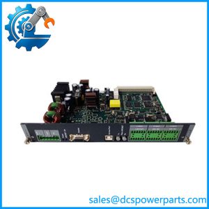
SCM-1 is the board that actually touches the generator. Everything else in a DELOMATIC 3 rack works in the low-voltage world of contacts, loops and logic; this module takes the machine’s three-phase currents through internal current transformers, two three-phase voltage inputs — generator and busbar — and, from those, produces the measurements, the protection decisions, the synchronising judgement and the breaker command that put a generator on the bus.
It is three instruments in one 18 TE slot. The multi-transducer measures and calculates line and phase voltages, the three line currents, generator and busbar frequency, apparent, active and reactive power and power factor, with Class 1 accuracy to IEC 688 and harmonics included up to 500 Hz. The synchroniser compares generator and busbar and decides the instant of paralleling. The breaker control unit supervises position feedback on two potential-free inputs and issues ON and OFF through two potential-free relay outputs rated 250 V / 5 A / 1000 VA on AC and 250 V / 1 A / 50 W on DC. One SCM-1 serves one generator set, and only one may be fitted per DGU.
The synchronising strategy is the detail that separates this module from a generic check-sync relay. Paralleling is dynamic and deliberately over-synchronous: the frequency offset is applied so the incoming machine is slightly fast and picks up load the moment the breaker closes, rather than floating in at exact equality and motoring briefly. Closing is permitted only when the voltage difference is inside a programmable ΔU, and only when the phase angle is coherent with respect to the breaker’s closing time, which is itself a programmable value. That last point makes the setting a property of the breaker as much as of the generator: after a breaker overhaul or a mechanism change, the closing time moves and the Δangle setting has to be re-checked, because the module is predicting where the phase will be when the contacts actually touch.
Two constraints are stated flatly in DEIF’s data and are routinely missed by people buying a spare. First, only speed droop governors may be used in connection with the SCM-1 synchroniser. A governor configured for isochronous operation does not present the droop characteristic this synchronising scheme expects, and the result is a set that will not settle into load sharing. Second, the voltage measuring range is selected by jumpers on the printed circuit board — low for 100–200 V, medium for 201–379 V, high for 380–690 V, each ±20 % — while the current transformer ratio, −/1 A or −/5 A, is selected in the application program. Hardware for one quantity, software for the other: a board lifted from a 400 V machine and fitted to a 690 V one will measure plausibly and wrongly until someone moves the jumper.
The measurement front end is built for real machines. Current inputs accept −/1 or −/5 A with a crest factor up to 6, present a burden of about 0.3 VA per phase, and withstand 10 A continuously, 75 A for ten seconds and 300 A for one second. Voltage inputs, at 0.5 VA per phase, tolerate twice nominal for ten seconds and take 690 V AC directly; anything above that needs voltage transformers. Wiring may be four-wire with neutral or three-wire without, in which case terminals 10 and 14 are left unused and must not be grounded. The current inputs take 4 mm² conductors and carry the warning that matters: short the CT circuits before disconnecting, because the module contains the current transformers.
Its outputs to the machine come in two flavours. Electronic speed governors and AVRs are driven from analogue outputs of −20…0…+20 mA at up to 5 V DC — a 0…5 V span is obtained by paralleling the circuit with a 250 Ω resistor. Mechanical governors and mechanical AVRs are driven by relay outputs, fitted as options, and DEIF is explicit that fitting the mechanical speed-governor relays deactivates the corresponding analogue outputs and brings terminals 33–40 into use. Where those pilot motors are used, a 0.1 µF capacitor across the motor terminals is required — an X-capacitor for AC pilot motors, a tranzorber or equivalent for DC.
Power comes in two ways. The board is fed from the PSM-1 backplane like any other module, drawing 2.0 W typical and 3.0 W maximum, and it also has its own “SUPP” connector on a separately fused 24 V DC feed, 2.0 W typical and 4.0 W maximum, protected against transients and never to exceed 32 V DC. That second supply is not decoration: DEIF requires the SCM-1 supply to be fused separately to secure switchboard control, which is the mode in which the module keeps manual governor control available even when the automatic power-management side is not running.
Isolation is the highest in the rack — 2.5 kV, 2.0 kV and 1.0 kV test levels at 50 Hz for one minute to GL, LR and DNV practice — because this is the board that brings 690 V into a low-voltage cabinet. One red LED, BREAKER ON PULSE, reports the closing command being issued. The card is 91.4 mm wide, 1.25 kg, IP20 in the rack, rated to -25 °C operational with HSE climate class, and the system carries CE marking and type approval from LR, GL, DNV, ABS, BV, RINA and CNK.
DEIF has placed DM-3 at end of life with no direct replacement, so SCM-1 is today the hardest-working spare in a Delomatic cabinet: the board whose failure takes a machine off the bus entirely.
Technical Specifications
| Parameter | Value |
|---|---|
| Model | SCM-1 |
| Manufacturer | DEIF A/S, Denmark |
| Product type | Synchronising, measuring and breaker-control module for one generator set |
| Functions | Multi-transducer, dynamic synchroniser, generator breaker ON/OFF control, generator protection (I>, P>, −P>), busbar supervision (UBB>, UBB<, fBB>, fBB<) |
| Current inputs | 3-phase, −/1 A or −/5 A, ratio selected in the application program; crest factor 6; burden approx 0.3 VA per phase |
| Current overload | 10 A continuous, 75 A for 10 s, 300 A for 1 s |
| Voltage inputs | Two 3-phase groups, generator and busbar; ranges 100–200 V, 201–379 V, 380–690 V AC phase-phase ±20 %, selected by PCB jumpers |
| Voltage limits | 690 V AC maximum direct input; higher voltages require transformers; 2 × UN for 10 s overload; crest factor 1.5 |
| Measurement | Class 1 per IEC 688, -10 to +55 °C; frequency 40–70 Hz; harmonics to 500 Hz included |
| Synchroniser | Dynamic, over-synchronous; ΔU and Δangle programmable, Δangle referenced to breaker closing time; accuracy ±5° el.; 45–65 Hz |
| Analogue outputs | −20…0…+20 mA at max 5 V DC for electronic governor (ESG) and AVR (EAVR); 0…5 V via 250 Ω in parallel |
| Relay outputs | Generator breaker ON/OFF, and optional MSG / MAVR sets: 250 V, 5 A, 1000 VA AC; 250 V, 1 A, 50 W DC |
| Supply | Backplane from PSM-1, 2.0 W typical / 3.0 W max; plus separate SUPP feed, 24 V DC +30 % / −25 %, 2.0 W typical / 4.0 W max, external fuse max 2 A slow blow |
| Isolation | Test voltage 2.5 kV / 2.0 kV / 1.0 kV, 50 Hz, 1 minute, to GL / LR / DNV practice |
| Dimensions / weight | 91.4 mm wide (18 TE); 1.25 kg |
| Indication | Red LED BREAKER ON PULSE while the generator breaker ON command is sent |
| Approvals | CE marking; system type approval by LR, GL, DNV, ABS, BV, RINA and CNK |
| Lifecycle status | DM-3 platform at end of life at DEIF; no direct replacement |
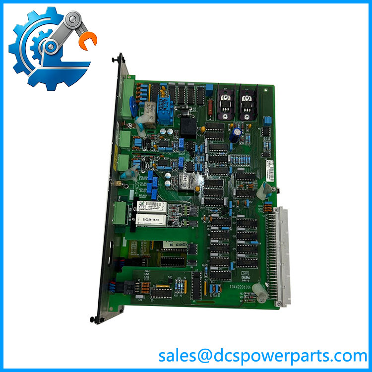
DEIF SCM-1
Key Features and Advantages
One board for measurement, synchronising, protection and breaker command: replaces a multi-transducer, a check-sync relay, a breaker control interface and several protection relays with a single 18 TE module that already shares its data with the CM-2 over the backplane. Fewer devices, one calibration reference, one wiring set.
Over-synchronous closing that takes load on the nail: the deliberate frequency offset means the incoming set is loaded the instant the breaker closes rather than motoring for a few cycles. On a plant where machines are started against a live bus under load, that behaviour is the difference between a clean transfer and a frequency dip every time.
Closing time treated as part of the setting: Δangle is referenced to the breaker’s own closing time, so the module predicts phase position at contact touch instead of at command. It is the correct engineering approach and a maintenance obligation — a serviced breaker invalidates an old setting.
Measurement good enough to bill against: Class 1 to IEC 688, harmonics to 500 Hz included, both −/1 and −/5 CTs, 690 V direct, crest factor 6 on current. That is instrumentation-grade for plant values, and it means kW, kvar and PF come from the same board that decides paralleling.
High isolation where it matters: 2.5 kV test level on a board that sits one wire away from 690 V. Nothing else in the rack needs it; this one does, and it is specified rather than assumed.
Separately fused control supply for degraded operation: the SUPP feed lets keep manual governor control alive in switchboard mode when the automatic side is unavailable. On a vessel that is the difference between a machine that can still be run by hand and a machine that cannot be started at all.
Outputs for old and new machines: analogue ESG/EAVR for electronic governors and AVRs, optional relay MSG/MAVR for mechanical ones, with a documented capacitor requirement across pilot motors. A single board type covers both generations of machine — though not both at once, since fitting the relays deactivates the corresponding analogue outputs.
Busbar supervision built in: UBB>, UBB<, fBB> and fBB< mean the module refuses to close onto a dead, over-voltage or off-frequency bus rather than trusting the operator to notice.
Compact for what it carries: 18 TE and 1.25 kg for four instruments’ worth of function, at 4 W maximum from the backplane.
Repairable where it counts: on a platform without a successor, a correct is what lets a generator set rejoin the bus instead of the machine being retired with the control system.
Applications
Ship generator sets paralleling onto the main switchboard: the archetypal case, where each machine’s measures its own generator and the busbar, synchronises onto a live board, controls speed and voltage, and supervises busbar voltage and frequency before permitting a close. Shaft-generator and bus-tie duties belong to SCM-2, but the generator-side function is this board.
Land-based multi-genset power stations: prime and standby plants where unit after unit is brought onto a common bus, load is shared through droop behaviour and the synchroniser’s over-synchronous strategy, and where breaker position feedback must be trustworthy because the module’s next decision depends on it.
CHP and industrial captive generation: plants where a generator is paralleled with a utility or with other machines and the voltage/reactive-power loop is as important as frequency, and where the same board supplies the kW, kvar and PF the plant’s reporting depends on.
Island and isolated grids: systems with no strong utility reference, where busbar supervision matters more than anywhere else — closing onto a collapsed or off-frequency bus is how an entire plant goes dark.
Marine auxiliary and offshore installations: certified switchboards where the module’s 2.5 kV isolation, type approvals and documented synchronising behaviour form part of the approved arrangement, and where a replacement has to reproduce the original settings, not approximate them.
Retrofit and repair of existing DGUs: the practical driver — a machine that cannot be put back on the bus because its has failed, where the board must arrive with the right voltage-range jumper setting, the right optional relay fit and the correct synchronising parameters for a breaker whose closing time is known.
Related Products
SCM-2 — synchronising and measuring module for shaft generators and busbar tie breakers; up to three per DGU, same measurement family, different application target. CM-2 — control module; holds the synchronising settings and receives the measurements over the backplane bus. PSM-1 — power supply module; feeds the backplane supply, while the separate SUPP feed is fused independently. IPM-1 — 16-channel universal input module; carries the non-electrical permissives that surround a start. OPM-1 — relay output module; supplemental command and alarm outputs on the same contact ratings as the breaker relays. AOM-1 — 8-channel analogue output module; additional analogue references where more than the governor and AVR loops are needed. CRM-1 — current protection relay module, for short-circuit, ground-fault or differential protection using its own current inputs. PRM-1 — protective relay module for mains voltage, frequency and negative-sequence conditions. CP-1 — control panel; where the synchronising and protection settings are viewed and changed. Voltage and current transformers — required above 690 V AC and for CT ratios beyond the internal −/1 A and −/5 A inputs.
Installation and Maintenance
Before installation: match the board to the machine before it goes anywhere near the cubicle. Confirm the generator’s phase-to-phase voltage and set the PCB jumpers to the correct range — low 100–200 V, medium 201–379 V, high 380–690 V — because this is hardware, not software, and a board set for a 400 V machine will measure wrongly on a 690 V one while looking perfectly healthy. Confirm the CT ratio in the application program (−/1 A or −/5 A) rather than assuming it matches the previous board. Check that the fitted options suit the machine: analogue ESG/EAVR outputs for electronic governors, relay MSG/MAVR for mechanical ones, remembering that fitting the mechanical relays deactivates the corresponding analogue outputs and uses terminals 33–40. Verify the governor is set for speed droop, since isochronous governors are not compatible with this synchroniser.
Wiring and commissioning: use 4 mm² on the current inputs and 2.5 mm² elsewhere, keep the 690 V circuits physically separated from the low-level wiring, and leave terminals 10 and 14 unused and ungrounded on a three-wire system without neutral. Short the CT circuits before disconnecting anything on terminals 1–6 — the module contains the current transformers and an open secondary is a hazard. Fit the separate 2 A slow-blow fuse on the SUPP feed as DEIF requires for switchboard control, fit the 2 A slow-blow fuse on the measuring circuit, and add the 0.1 µF capacitor across pilot-motor terminals where mechanical governors or AVRs are used. Then set ΔU, Δangle and the breaker closing time from the actual mechanism, and prove the synchroniser by observing the closing — the BREAKER ON PULSE LED confirms the command, but only a load check confirms the phase prediction was right.
Maintenance practice: treat breaker closing time as a calibrated value and re-verify the Δangle setting after any breaker overhaul, spring change or mechanism service. Inspect the pilot-motor capacitors and the MSG/MAVR relay contacts, since those carry inductive load and are the wear items on this board. Re-check the voltage jumpers and CT ratio whenever a board is moved between machines, and record both in the panel documentation so the next engineer does not have to infer them. Verify busbar supervision settings against the plant’s actual abnormal-bus conditions rather than leaving factory values, and after any CT or VT work confirm the measured values against a reference instrument — Class 1 accuracy is only meaningful if the transformers and burdens behind it are right.
Warranty and Quality
Each is supplied as the DEIF DELOMATIC 3 synchronising and measuring module with the voltage-range jumper setting, CT ratio assumption, optional relay fit and fuse requirements confirmed against the buyer’s machine and rack before dispatch — because a board that is electrically perfect and set for the wrong voltage class will synchronise a generator onto the bus with the wrong numbers. Units are inspected for current-transformer and terminal condition, jumper and option configuration, relay and contact state, LED function and marking legibility, and evidence of prior insertion or rework; where a DM-3 test arrangement is available, modules are powered on both backplane and SUPP supplies and checked for measurement accuracy against a reference source, analogue and relay output behaviour, breaker command and feedback logic, synchroniser response across 45–65 Hz, and isolation at the stated 2.5 / 2.0 / 1.0 kV test levels. A 12-month repair, replacement or refund commitment applies to the module. Support covers what this board actually raises: which voltage jumper setting the machine needs, how to confirm the CT ratio, why an isochronous governor will not work, how to set Δangle against breaker closing time, when to fit pilot-motor capacitors, how to keep switchboard control alive on the separate supply, and what DEIF’s end-of-life position means for a machine that still has to be put back on the bus.