Description
DEIF PCM 4.3 | Delomatic 400 Power Supply & Main Control Module
Key Technical Specifications
| Parameter | Specification |
|---|---|
| Manufacturer | DEIF A/S |
| Model | PCM 4.3 |
| System | Delomatic 400 / DM-400 |
| Product Type | Power supply and main control module |
| Rack Position | Leftmost module |
| Module Width | 8 TE / 40.64 mm |
| Input Supply | 18–36 VDC |
| Maximum Input Current | 6 A |
| Digital Relay Output | NO contact, 24 VDC / 8 A; documentation also specifies 250 VAC capability |
| Digital Input | Potential-free contact, 5 V / 7.5 mA |
| CAN Interfaces | 3 independent CAN buses |
| CAN Speed | 125 / 250 kbit/s in the cited DM-400 data sheet |
| RS Interface | 1 × RS-422/485 |
| RS Baud Rate | 4,800–57,600 baud |
| ARCNET | 1 × electrical or optical, 2.5 Mbit/s |
| Ethernet | 10/100 Mbit/s |
| Display Interface | TTL serial interface |
| Service Interface | USB |
| Processor | 180 MHz |
| Operating System | Linux 2.6 |
| SDRAM | 64 MB |
| Nonvolatile RAM | 32 KB |
| Flash | 16 MB shared program/data storage |
| Protection Class | IP20 |
| Module Function | Rack power, main control, application execution, inter-module communication |
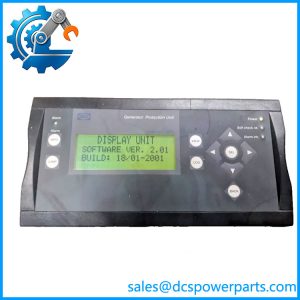
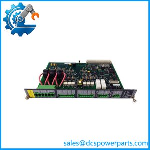
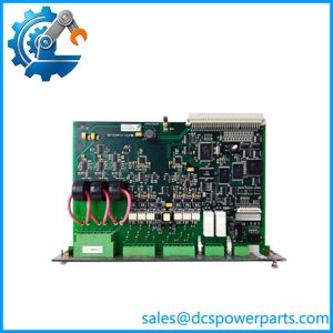
DEIF specifies PCM 4.3 as the power supply and main control module. It supplies the other rack modules and manages data exchange through the backplane; the application software and communication interfaces are also located on the PCM.
Product Introduction
The DEIF PCM 4.3 is the central processing and power module of the Delomatic 400 control platform. It is installed in the leftmost position of the 19-inch rack and provides the DC power distribution required by the other DM-400 modules while managing their backplane communications. DEIF documentation identifies the PCM 4.3 as the module containing the main control unit and application software.
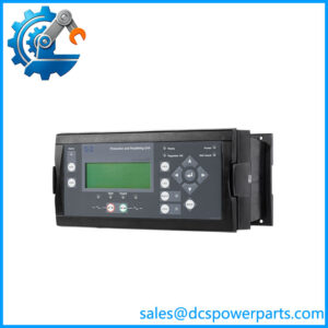
In a generator or turbine installation, the PCM 4.3 sits above the individual measurement and I/O functions. Modules such as SCM 4.1 handle AC measurement and synchronization-related signals, while IOM 4.2 handles general analog and digital field signals. The PCM coordinates these modules and provides the external communication interfaces needed by the plant-control system.
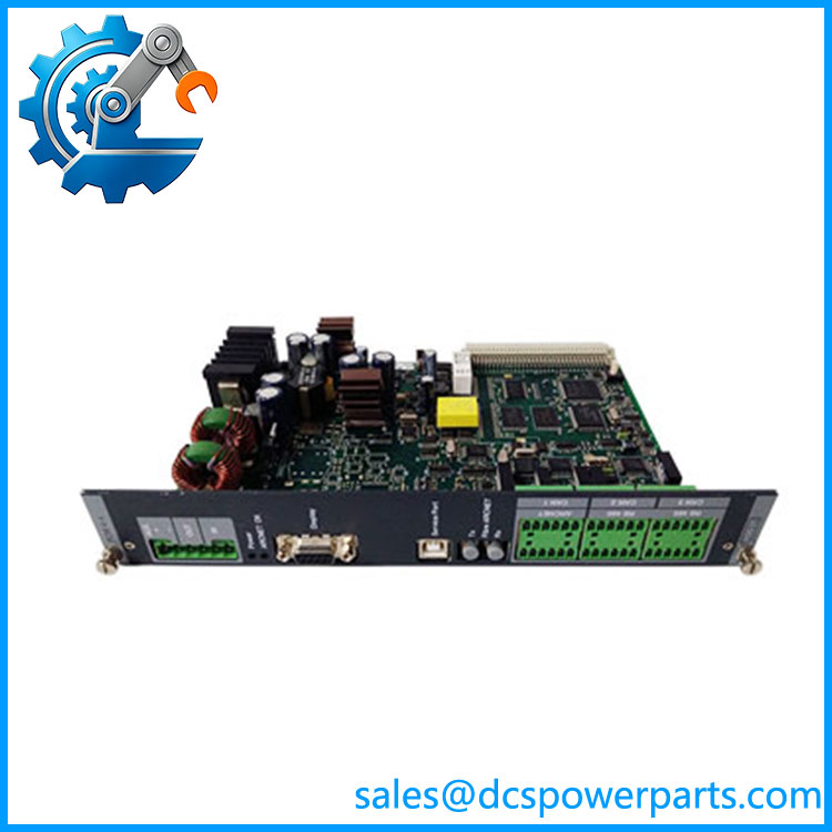
PCM4.3
Application Scenarios & Field Pitfalls — Engineer’s Perspective
Engineering Pain Point
A failed PCM 4.3 is a system-level failure rather than a simple I/O failure. Because the module provides both rack power and main application control, loss of the PCM can affect communication and operation across the Delomatic system.
Typical Applications
- DEIF Delomatic 400 DM-400 generator controllers
- Gas-engine generator control systems
- Hydro turbine generator control systems
- Generator synchronization and power-management applications
- Industrial and marine power-generation control panels
The DM-400 architecture uses PCM 4.3 together with SCM 4.1 and IOM 4.2 modules in a modular 19-inch rack. DEIF documentation lists 24 TE, 42 TE, and 60 TE rack configurations depending on the number of modules installed.
Technical Pitfalls to Avoid
- Do not confuse PCM 4.3 with SCM 4.1.
PCM 4.3 is the main power/control module, whereas SCM 4.1 is the AC measurement and synchronization/protection module. Their functions are fundamentally different. - Verify the DC supply before installing a replacement.
DEIF specifies 18–36 VDC with a maximum input current of 6 A. The installation manual also notes that systems requiring compliance with power-supply dip requirements may need battery-backed 24 VDC. - Preserve the application configuration.
The application software resides in the PCM 4.3. A physically matching replacement therefore does not necessarily reproduce the original plant configuration without the correct application/software setup. - Check the communication topology.
The PCM provides CAN, RS-422/485, ARCNET, Ethernet, display, and service interfaces. Wiring and configuration should be documented before removing the existing module.
Related Products
- DEIF SCM 4.1 — AC measuring and fast-protection module for Delomatic 400; handles generator and mains/busbar electrical measurements.
- DEIF IOM 4.2 — Multifunction I/O module providing analog, temperature, digital, and RPM-related field interfaces.
- DEIF PCM 4.4 — Controller/power module used for extension racks; communicates with the main rack through ARCNET.
- DEIF DM-400 — Complete Delomatic 400 control platform using PCM, SCM, and IOM modules.
- DEIF Delomatic 400 Gas — DM-400 configuration intended for gas-engine generator applications.
- DEIF Delomatic 400 Hydro — DM-400 configuration for hydroelectric turbine-generator applications.
- DEIF 19-inch DM-400 Rack — Mechanical rack accommodating PCM, SCM, and IOM modules.
- DEIF IOM 4.x modules — Field-interface modules that operate under the main PCM control architecture.
Procurement & Replacement Check
Before purchasing a DEIF PCM 4.3, verify:
- Exact designation: PCM 4.3
- Delomatic generation: DM-400 / Delomatic 400
- Gas, hydro, or other application variant
- Existing rack width and module arrangement
- DC supply: 18–36 VDC
- Application software and configuration backup
- CAN network wiring and addresses
- ARCNET connection
- Ethernet configuration
- RS-422/485 connections
- Display/service connections
- Existing SCM 4.1 and IOM 4.2 modules
- Firmware/software compatibility
- Condition of the backplane connector
Recommended procurement description:
DEIF PCM 4.3 Power Supply and Main Control Module, Delomatic 400 DM-400, 18–36 VDC, 180 MHz Processor, 3× CAN, RS-422/485, ARCNET, Ethernet, 8 TE Rack Module.
The key distinction is straightforward: PCM 4.3 is the central power and control module of the DEIF Delomatic 400 system. It is not merely a power supply; it also contains the main control unit, application software, and major communication interfaces that coordinate the rack.