Description
Product Overview
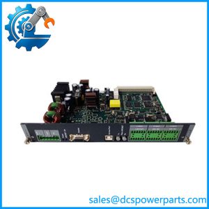
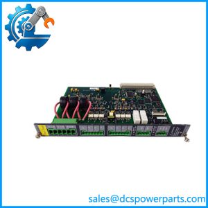
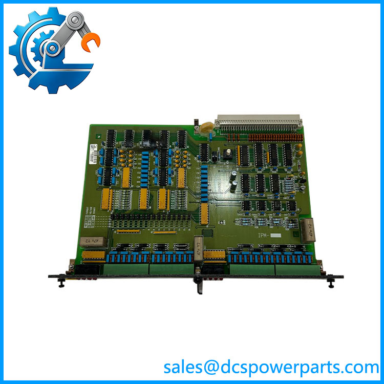
OPM-1 is the output board of a DELOMATIC 3 generator unit. Sixteen channels, every one of them a relay with a potential-free contact, sitting in a DGU rack beside the CM-2 that drives it and the IPM-1 boards that report back. Where the input module reads what the plant is doing, the OPM-1 does what the plant is told: start and stop commands to the engine, close and open commands to contactors, alarm and trip outputs to the annunciator, indication to panel lamps, and drive signals to any actuator that expects a dry contact rather than an analogue reference.
The board’s usefulness comes from that word “potential-free”. Each channel is an isolated contact pair, not a sourcing or sinking transistor output, so it can be wired into a 24 V DC control circuit, a 230 V AC alarm circuit or a 110 V DC trip circuit without a jumper or a polarity decision. The plant’s own voltages are switched, not the module’s supply, which is the arrangement marine and industrial switchgear is built around.
The constraint that matters most is written in two lines of the DEIF documentation and is routinely ignored. The contact rating is a maximum of 250 V, 5 A, 1000 VA on AC — and 250 V, 1 A, 50 W on DC. That second figure is the one that catches people. Fifty watts at 220 V DC is 0.23 A, so a breaker trip coil or a DC contactor coil rated at half an amp cannot be switched directly by this board no matter how small the current looks beside the 5 A AC figure. AC loads carry their own ceiling: 250 V at 5 A is 1250 VA, above the 1000 VA limit, so at full voltage the permitted current is around 4 A — and that is resistive current. A contactor coil or a small motor presents an inductive load with inrush several times its sealed current, and the VA rating is what gets exceeded first.
None of this makes the module weak; it makes it a control-level output. The correct engineering response is an interposing relay or contactor for anything with a coil, a motor or a DC trip circuit, and the OPM-1 then drives the interposing coil — a load comfortably inside the rating and one that also puts the arc energy outside the rack. Sites that wire the trip coil straight to the board discover the 50 W limit as a welded contact and an uncleared fault, usually during the first real trip test rather than during commissioning.
Which channel does what is decided entirely in the application program running in the CM-2. The board carries no per-channel function selector, no label that survives a reconfiguration, and no indication of whether channel 9 is a horn output or a breaker close command. The wiring schedule and the program listing are the only authority, which is why a spare OPM-1 fitted into the wrong slot in a rack will click convincingly and operate the wrong devices.
Up to eight OPM-1 boards can be fitted in one DGU — 128 relay outputs — but the rack width fills long before that figure means anything: 84 TE of module space, shared with every input, analogue and protection board in the unit. In practice a DGU carries one or two relay boards, and the rest of the output count is met by the relay outputs built into the SCM-1 and SCM-2 boards for breaker commands, and by the four relay outputs on each CP-1 panel.
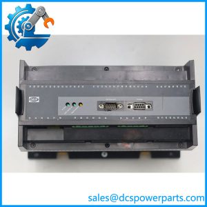
Physically the board is a plug-in module with removable connectors, supplied from the PSM-1 through the backplane, in a rack built to BN 411002 and BN 411003 and rated IP20 with cover plates on unused slots. The system carries CE marking and type approval from LR, GL, DNV, ABS, BV, RINA and CNK, and operates to -25 °C with HSE climate class — the numbers that let the rack live in a switchboard room.
DEIF has placed DM-3 at end of life with no direct replacement, so the OPM-1 today is an installed-base spare: the board that keeps a running generator unit able to command its own switchgear.
Technical Specifications
| Parameter | Value |
|---|---|
| Model / assembly code | , assembly code 1044220080 with a revision letter suffix |
| Manufacturer | DEIF A/S, Denmark |
| Product type | Relay output module for the DELOMATIC 3 DGU rack |
| Channel count | 16, all relay outputs |
| Contact type | Potential-free, isolated contact per channel |
| Contact rating, AC | Maximum 250 V, 5 A, 1000 VA |
| Contact rating, DC | Maximum 250 V, 1 A, 50 W |
| Module count per DGU | Up to 8 boards, sharing the rack’s module space with all other boards |
| Function assignment | Defined in the application program in the CM-2; no per-channel selector on the board |
| Supply | From the PSM-1 via the rack backplane |
| Terminals | Removable connectors, 2.5 mm² single or multi-stranded conductors |
| Rack / protection | BN 411002 / BN 411003 rack; IP20 with unused slots fitted with cover plates |
| Environment | Modules rated -25 to +70 °C operational, -40 to +70 °C storage, climate class HSE per DIN 40040 |
| Approvals | CE marking; system type approval by LR, GL, DNV, ABS, BV, RINA and CNK |
| Lifecycle status | DM-3 platform at end of life at DEIF; no direct replacement |
DEIF OPM-1
Key Features and Advantages
Potential-free contacts, both polarities: every channel is an isolated contact pair, so a 24 V DC control circuit, a 230 V AC alarm circuit and a 110 V DC indication circuit can all be driven from one board. No sourcing-versus-sinking decision, no shared common, no polarity errors at commissioning — the field side supplies its own voltage.
Honest ratings that define the application: 250 V / 5 A / 1000 VA on AC and 250 V / 1 A / 50 W on DC. Read properly, those two lines tell you exactly where this board belongs: control circuits, lamps, annunciators and interposing coils. Read carelessly, they produce a welded trip contact at the first real fault, which is the worst possible moment to learn the DC watt limit.
Sixteen outputs on one board: a generator unit’s command list — engine start/stop, fuel and lube-oil permissives, breaker commands via interposing relays, cooling pumps, pre-lube, alarms, common trouble and horn — fits on one or two boards instead of a wall of discrete relays. Fewer components, fewer terminals, fewer failures to trace.
Driven from the program, not from jumpers: the function of each channel lives in the CM-2 application, so changing a horn output to a lamp output is a program change and a wiring change, not a hardware change. That flexibility is also the reason the wiring schedule must travel with the rack.
Pluggable terminals and slot-keyed backplane: a board is replaced by unplugging the connector and sliding it out, without disturbing field wiring, in a rack where each connector’s guide rails keep a module from travelling where it does not belong.
Coordinated with the boards that already have relays: the SCM-1 and SCM-2 carry their own potential-free outputs for generator breaker ON/OFF commands on the same 250 V / 5 A / 1000 VA, 250 V / 1 A / 50 W basis, so the breaker path can be kept on the measuring board and the reserved for auxiliary and alarm duty.
Marine-grade mechanics and approvals: BN-standard rack, vibration kit standard in marine installations, IP20 with blanking plates, and classification-society type approval at system level — the combination that makes a relay board acceptable in a vessel’s switchboard room rather than merely functional.
Spares that are actually repairable: because the platform is at end of life, the is the difference between restoring a generator unit’s output side and condemning a switchboard that is otherwise sound.
Applications
Generator command outputs: engine start and stop, pre-lube and cooling-water pump commands, fuel and lubrication permissives, and the sequenced commands of an automatic start, all as dry contacts into the machine’s own control panel. This is the ‘s principal duty on any DGU.
Breaker and contactor control through interposing relays: generator breaker close and open, bus-tie operation and load-shedding contactor commands, where the board drives the interposing coil rather than the primary device coil — the wiring pattern that keeps the 50 W DC limit and the inductive inrush away from the module.
Alarm and annunciator outputs: common alarm, common trip, horn and lamp-test outputs to the panel and to a higher-level alarm system, plus group alarms routed to the plant’s own monitoring. Potential-free contacts let the board sit between a 24 V DC logic circuit and a 230 V AC annunciator without an interface.
Auxiliary and balance-of-plant switching: ventilation, heaters, fuel-transfer pumps, jacket-water and exhaust-related auxiliaries that are switched rather than modulated, on a machine whose control already lives in the DGU.
Marine power plants and offshore installations: switchboard rooms where the command circuits are the vessel’s own voltages, the rack is fitted with the vibration kit as standard, and the classification society expects the original approved configuration to be preserved when a board is replaced.
Land-based multi-genset plants, CHP and isolated grids: standby and prime-power installations where unit-level command outputs must keep working independently of the plant’s supervisory layer, and where a failed relay board on one machine must be repairable without re-engineering the cabinet.
Related Products
IPM-1 — 16-channel universal input module; the field-signal counterpart, configurable per channel as binary, current or voltage. AOM-1 — 8-channel analogue output module; provides the modulated references the cannot, such as speed and voltage set points. CM-2 — control module; holds the application program that assigns every channel and reports rack health through I/O OK. PSM-1 — power supply module; one per DGU, feeding the output boards through the backplane. SCM-1 — synchronising and measuring module for the generator, with its own potential-free generator breaker ON/OFF outputs on the same contact ratings. SCM-2 — synchronising and measuring module for shaft generators and busbar tie breakers, likewise carrying breaker command relays. CRM-1 — current protection relay module; up to four per DGU, configured as short-circuit, ground-fault or differential protection. PRM-1 — protective relay module for mains voltage, frequency and negative-sequence conditions; up to two per DGU. CP-1 — control panel; up to three per DGU, each with four relay outputs of its own plus sixteen instrument outputs. DGU rack — 84 TE or 60 TE backplane assembly in which the is installed, keyed and cover-plated.
Installation and Maintenance
Before installation: obtain the rack’s output schedule and the CM-2 application listing, and confirm which channel drives which device before the board goes in — the module has no function selector and no per-channel marking that survives a reconfiguration, so the wiring schedule is the only map. Check the load each channel will switch against both halves of the rating: 250 V / 5 A / 1000 VA AC and 250 V / 1 A / 50 W DC. Anything with a coil, a motor or a DC trip circuit gets an interposing relay, with the interposing coil as the load and the heavy circuit kept outside the rack. Confirm the board’s slot and that the backplane connector and guide rails are undamaged, and record the assembly code and revision letter before fitting the replacement.
Wiring practice: use the removable connectors so field wiring can be prepared outside the rack, keep AC and DC circuits in separate groups rather than sharing a multi-core cable, and fit suppression across DC coils — a diode across a DC coil, an RC network across an AC coil — because the module’s rating covers the load, not the switching transient. Protect each output circuit with its own fuse matched to the field wiring rather than relying on the board, and check that the terminals take no more than 2.5 mm² conductors. Leave every unused slot covered so the rack keeps its IP20 rating.
Maintenance practice: relay contacts are the wearing part, and they fail in two recognisable ways — increasing resistance across a closed contact that shows up as a device that will not pick up, and welding shut after an inductive or over-rated load, which shows up as a device that will not drop out. Test outputs against a real load at each major outage rather than by listening for the click, and record which channels have been re-tasked since the last wiring change. Triage faults by the CM-2‘s I/O OK indication first: a dark I/O OK with a healthy network means the rack no longer matches the program, not that a relay has failed. Keep a spare with the correct assembly code and revision letter, since the platform is out of production and a substitute board changes the approved configuration of the unit.
Warranty and Quality
Each is supplied as the DEIF DELOMATIC 3 relay output module with its assembly code and revision letter verified against the board marking and the buyer’s rack documentation confirmed, because a board that fits the slot and carries the wrong revision is not the spare the machine needs. Units are inspected for backplane connector condition, terminal-block integrity, relay and contact condition, label legibility and evidence of prior insertion or rework; where a DM-3 rack is available for test, modules are powered through the PSM-1 and checked for channel-by-channel operation of all sixteen outputs, contact continuity in the energised and de-energised states, coil behaviour on the interposing loads they will actually drive, and recognition by the CM-2 at the expected slot address. A 12-month repair, replacement or refund commitment applies. Support covers the questions this board actually raises: how to check a load against the AC and DC ratings, when an interposing relay is mandatory, how to suppress DC and AC coil transients without slowing the circuit, how to map outputs to the application listing, why a contact welds after a trip, and what DEIF’s end-of-life position means for a switchboard that still depends on DM-3.