Description
Product Overview
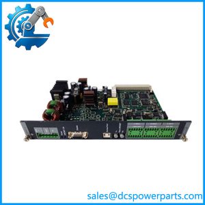
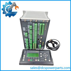
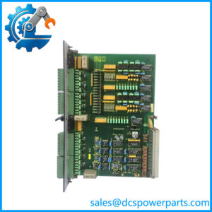
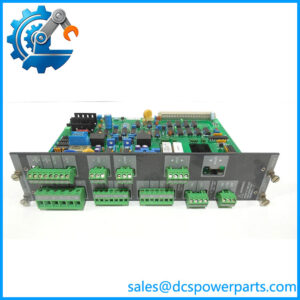
DELOMATIC-3 DGU-2 is not a catalogue part number in the sense the rest of a spare-parts list uses. In DELOMATIC 3 the DGU — DEIF Generator Unit — is a rack, and racks are issued per generator set: one DGU, one machine. The “2” identifies the second generator unit of a plant, which fixes its ARC-network node number and therefore which control panels belong to it. What sits inside the rack is defined by the application: a power supply module, a control module, and a combination of input, output, synchronising and protection boards chosen for that machine.
This is the unit that actually defines a power plant’s architecture. Each DGU-2 is a self-contained controller for generator set 2 — it measures, protects, synchronises, shares load and executes its own start sequence — and it does so without depending on a higher-level system being alive. Take the plant’s supervisory link away and the DGU still runs its machine. Take a CP-1 panel away and nothing changes, because the panels are slaves: all settings remain active in the DGU with the panel disconnected.
The rack itself is a mechanical and electrical standard rather than a generic enclosure. It is built to BN 411002 and BN 411003, comes in two usable widths — 84 TE and 60 TE of module space — and carries a backplane communication bus made of a flat cable and a run of 64-terminal connectors, each with its own set of PCB guide rails so a board can only travel where it belongs. Modules are delivered with removable connectors, which is what makes a board swap a field operation rather than a re-termination.
The published module ceilings are generous: up to eight IPM-1 input boards, eight OPM-1 relay output boards, eight AOM-1 analogue output boards, four CRM-1 protection boards, three SCM-2 boards, two PRM-1 boards, one SCM-1 and one CM-2. They are also, in practice, irrelevant — the rack runs out of width long before the type limits bind. Every module occupies a multiple of 6 TE, so an 84 TE rack accepts fourteen six-TE boards and a 60 TE rack accepts ten. A configuration with eight input and eight output boards is a specification exercise, not a rack that exists.
Two physical choices are made at ordering and are effectively irreversible afterwards: base mount or flush mount, and whether the vibration absorbent kit is fitted. For marine installations the kit is standard, adding 1.2 kg to an 84 TE rack or 0.9 kg to a 60 TE rack; for land plants it is optional and often omitted. The empty 84 TE rack weighs 3.5 kg, the 60 TE rack 3.0 kg, before any module goes in.
Coordination between units happens only over the ARC-network: a token-ring LAN carrying up to eight DGUs with their panels, and extending no further than the plant’s own cabling allows. Serial connectivity to a DCS, alarm system or Modbus master is not a rack feature — it is a piggyback communication module fitted onto the CM-2 in the DGU that carries the number whose data you want.
Unused slots must be closed with cover plates to hold the rack’s protection class, and the whole assembly is IP20 once that is done. That single sentence explains a great deal of what goes wrong in the field: a rack with a missing board and no blanking plate is both an EMC aperture and an airflow change, and the fault it causes rarely looks like either.
DEIF has placed the DM-3 platform at end of life with no direct replacement, so DGU-2 today exists as an installed assembly inside a running plant — the identity that has to be matched when a board inside it is replaced, and the configuration record that has to be preserved when the plant outlives the product line.
Technical Specifications
| Parameter | Value |
|---|---|
| Designation | DELOMATIC-3 DGU-2, generator unit no. 2 of a DELOMATIC 3 system |
| Manufacturer | DEIF A/S, Denmark |
| Product type | Assembled generator control rack (DGU) for one generator set |
| Rack sizes | 84 TE: A 426.7 mm, B 465.1 mm, C 483.0 mm, 3.5 kg — or 60 TE: A 304.8 mm, B 343.2 mm, C 361.1 mm, 3.0 kg |
| Rack construction | BN 411002 / BN 411003; backplane communication bus on flat cable with 64-terminal connectors and PCB guide rails |
| Mounting | Base mount or flush mount, specified at ordering |
| Vibration absorbent kit | 84 TE rack +1.2 kg; 60 TE rack +0.9 kg; standard for marine applications, optional for land plants |
| Module content | One PSM-1 and one CM-2 mandatory; IPM-1 max 8, OPM-1 max 8, AOM-1 max 8, CRM-1 max 4, SCM-1 max 1, SCM-2 max 3, PRM-1 max 2 |
| Control panels | Up to 3 CP-1 per DGU; slave units, settings remain active if a panel fails |
| Network | ARC-network token ring; up to 8 DGUs with corresponding panels per network |
| Serial interface | Through a CM-2 piggyback communication module: RS-232, RS-422 or RS-485, Modbus RTU |
| Supply | 24 V DC at the PSM-1, +25 % / −25 % including ripple; some modules require a separate supply for safety functions |
| Protection / environment | IP20 with unused slots fitted with cover plates; modules rated -25 to +70 °C operational, climate class HSE per DIN 40040 |
| Approvals | CE marking; system type approval by LR, GL, DNV, ABS, BV, RINA and CNK |
| Lifecycle status | DM-3 platform at end of life at DEIF; no direct replacement |
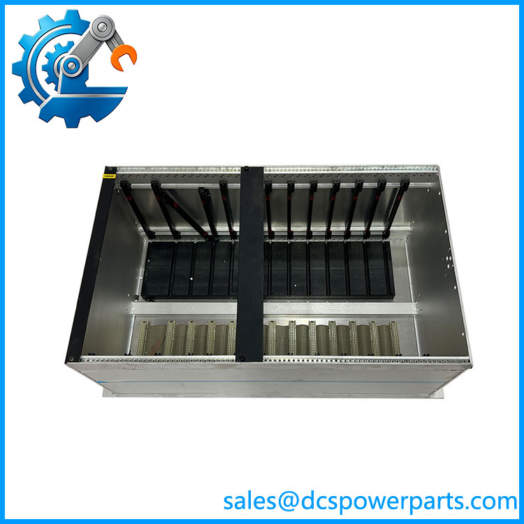
DELOMATIC-3 DGU2
Key Features and Advantages
One rack, one machine, no shared brain: DGU-2 owns generator set 2 outright — control, protection, measurement, synchronising and load sharing all execute inside the rack. There is no plant-level controller whose failure stops every unit at once, which is the architectural reason this platform survived so long in marine and island plants.
A configuration, not a catalogue number: because the DGU is an assembly, the specification is the module list, the rack width, the mounting style and the node number. Sites that understand this can rebuild or extend a rack from boards; sites that treat “DGU-2” as a single SKU order something that arrives empty, or arrives full of another plant’s configuration.
Rack capacity is the real ceiling: the type maxima — eight input boards, eight output boards — cannot be reached inside an 84 TE rack that holds fourteen six-TE modules. Planning by type limit rather than by width is how a cabinet design ends up with a specification the hardware cannot carry.
Panels that can fail without stopping the plant: up to three CP-1 units per DGU, all slaves. Alarm display, parameter access and instrument outputs are on the panel; the settings and the automatic functions are in the DGU. Losing a panel costs visibility, not control.
Backplane addressing that makes diagnostics possible: every module sits at a known internal address, and the CM-2‘s I/O OK indication validates the whole rack configuration in one lamp. A board in the wrong slot, a board type the application does not expect, or a slot left empty all produce the same clear answer.
Removable connectors as a maintenance property: modules ship with pluggable terminal blocks, so a failed board is unplugged and replaced without disturbing field wiring — the difference between a one-hour repair and a re-termination with a commissioning witness.
Physically honest for marine work: BN-standard rack, base or flush mounting, and a vibration kit that is standard on marine installations rather than an afterthought. In a switchboard room the rack is bolted, damped and covered, and the protection class is restored by blanking plates rather than assumed.
Network discipline that scales to eight machines: a token-ring ARC-network with defined node numbering, so load sharing between units is a matter of addressing, and the second DGU on a plant is a node, not an ambiguity.
Serial integration where it belongs: RS-232, RS-422 or RS-485 Modbus RTU through the CM-2, per unit. A DCS can read one machine’s data without a gateway per rack, and the protocol choice does not force a controller change.
Applications
Ship power plants with multiple generator sets: the classic case, where each machine in the switchboard room has its own rack and its own panels, all coordinated over the ARC-network for load sharing and blackout prevention. Marine installations take the vibration kit as standard and the classification society approval as a condition of service.
Land-based power stations and standby plants: diesel and gas multi-genset installations where unit 2 is the second machine in a parallel group, with its own start sequence, breaker control and protection, and its own panel at the local operating position.
Local cogeneration and CHP: plants where a generator set runs against process steam or heat demand, and the DGU executes the permissives and load limits that keep the machine inside its operating envelope while the plant’s heat balance changes.
Island and isolated grids: ports, mines, factories and remote communities running several units with no strong utility, where per-unit racks plus a shared network replace a central controller that would otherwise be a single point of failure for the entire supply.
Marine auxiliary and offshore installations: certified switchboards where the approved configuration includes the rack’s module list and its panel arrangement, and where a substitute assembly changes the compliance basis rather than merely the hardware.
Life extension and staged retrofit of existing plants: the reality behind most orders today — a that needs a board, a panel or a complete rebuild on the original mechanical footprint, where the requirement is to reproduce the existing rack, its module list and its node identity rather than to modernise it in place.
Related Products
PSM-1 — power supply module; mandatory, one per DGU, supplying all modules through the backplane. CM-2 — control module; mandatory, one per DGU, carrying the application program in two flash PROMs and the ARC-net node identity. IPM-1 — 16-channel universal input module; up to eight per DGU, each channel binary, current or voltage. OPM-1 — 16-channel relay output module; up to eight per DGU, potential-free contacts for commands and alarms. AOM-1 — 8-channel analogue output module; up to eight per DGU, bipolar or unipolar voltage and current outputs. CRM-1 — current protection relay module; up to four per DGU, configured as short-circuit, ground-fault or differential protection. SCM-1 — synchronising and measuring module for the generator; one per DGU, with protection, breaker control and precision synchroniser. SCM-2 — synchronising and measuring module for shaft generators and busbar tie breakers; up to three per DGU. PRM-1 — protective relay module for mains conditions such as voltage, frequency and negative sequence; up to two per DGU. CP-1 — control panel; up to three per DGU, addressed to the unit whose node number it matches. DM-4 / PPM 300 — later DEIF power management platforms; the migration direction, with no direct one-for-one replacement for DM-3.
Installation and Maintenance
Before installation: establish the rack’s full identity, not just “” — rack width in TE, base or flush mounting, vibration kit fitted or not, the module list with each board’s slot position, the CM-2‘s node-ID switch setting, and the number and addressing of the CP-1 panels that belong to this unit. Confirm the 24 V DC feed to the PSM-1 including ripple and tolerance, and identify any module that needs its own supply for a safety function. On a replacement rack, check that the footprint and mounting holes match the cabinet’s existing cut-out, because an 84 TE rack and a 60 TE rack are not interchangeable on a wall.
Mechanical and electrical checks: install base or flush per the cabinet design, secure the vibration kit where marine practice requires it, and keep the clearance the panels need in front of the rack so the cabinet door closes over protruding connectors. Wire the field circuits to the removable connectors before seating the boards where practical, keep the ARC-network coaxial runs clear of power cables with the specified minimum spacing between nodes, and fit cover plates on every unused slot as the rack is closed — the protection class depends on it.
Maintenance practice: hold the module list as the rack’s controlling document, with slot positions and board types recorded, because a cannot be restored from its name alone. Triage faults by unit first, then by module: a dark I/O OK on the CM-2 with LAN OK lit means the rack no longer matches the application, not that the controller has failed. Replace one board at a time, power down for the swap, and power-cycle after any node-ID or dip-switch change. Keep the panels’ addressing consistent with the DGU number so alarms continue to appear at the correct operating position, and archive the CM-2‘s PROM pair as the plant’s most fragile asset.
Warranty and Quality
Each DELOMATIC-3 is supplied as a rack assembly built to the buyer’s recorded configuration — rack width, mounting style, vibration kit, module list with slot positions, node identity and panel arrangement — with the module content confirmed line by line before dispatch, because a rack that is correct in outline and wrong in one board type will refuse to reach I/O OK and will be blamed on the controller. Assemblies are inspected for backplane and connector condition, guide-rail and slot integrity, cover-plate completeness, enclosure and earthing, and evidence of prior installation; where a DM-3 system is available for test, racks are powered through the PSM-1 and checked for module recognition, I/O OK behaviour against the declared list, LAN OK on the ARC-network, and panel-to-DGU addressing. A 12-month repair, replacement or refund commitment applies. Support covers the questions this assembly actually raises: how to turn “” into an orderable specification, which module ceilings matter and which are irrelevant, how to plan slots against TE width, how to set and preserve node identity, how to restore protection class on a partially populated rack, and what DEIF’s end-of-life position means for a plant that still runs on DM-3.