Description
Product Overview
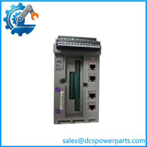
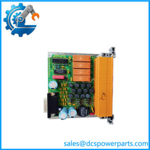
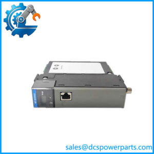
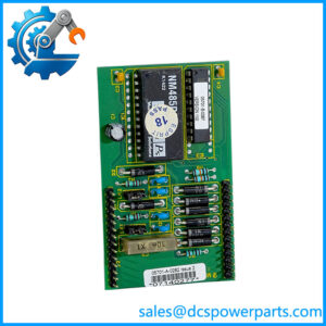
The Honeywell TK-PRR021 is a controller redundancy module used with Honeywell Experion PKS C200 systems. Its primary purpose is to support a redundant C200 controller architecture rather than perform conventional analog or digital I/O processing. The module occupies two chassis slots and provides the hardware path required for C200 redundancy. Published technical data identifies a 24 VDC current draw of 90 mA, with additional internal supply requirements of 1.0 A at 5 VDC, 0.75 A at 3.3 VDC, and 0.007 A at 1.2 VDC.
For Honeywell TK-PRR021, the important engineering distinction is that it is a redundancy component, not a standalone controller. The C200 application logic remains within the controller architecture; the TK-PRR021 provides the redundancy function required for the paired-controller arrangement. Honeywell’s part number is commonly identified as 51309288-275, so procurement records should retain both the functional model and the complete hardware number.
The Honeywell TK-PRR021 is particularly relevant when maintaining an existing C200 installation where controller redundancy is already part of the plant design. The module should be evaluated together with the C200 controllers, chassis, redundancy connections, and system firmware. To be completely transparent, a replacement module that merely powers up is not sufficient evidence of compatibility; the redundant-controller architecture should be tested under controlled conditions before the spare is released for operational service.
Product Introduction
A redundant installation depends on more than having two processors installed side by side. TK-PRR021 provides the dedicated redundancy-module function and occupies two chassis slots, with a documented 24 VDC current draw of 90 mA.
For a Honeywell Experion PKS redundancy replacement, verify the chassis arrangement, controller pair, firmware, and redundancy configuration before commissioning. The module is an architectural component, not a generic spare controller.
Key Technical Specifications
| Parameter | Value |
|---|---|
| Manufacturer | Honeywell |
| Model | TK-PRR021 |
| Part Number | 51309288-275 |
| Product Type | Redundancy Module |
| Application | Controller Redundancy |
| Product Family | Experion PKS |
| Controller | |
| Primary Supply | 24 VDC |
| Current Draw @ 24 VDC | 0.090 A |
| Current Draw @ 5 VDC | 1.000 A |
| Current Draw @ 3.3 VDC | 0.750 A |
| Current Draw @ 1.2 VDC | 0.007 A |
| Chassis Slots | 2 |
| Approx. Weight | 0.45 kg |
| Function | Controller redundancy interface |
| Installation | chassis |
| Condition | New Surplus — verify revision and system compatibility |
The electrical and chassis requirements are supported by published TK- technical listings.
Related Products
- Controller — The primary controller platform supported by TK-. The redundancy module should be evaluated as part of the complete redundant-controller architecture.
- Redundancy Chassis — Provides the physical architecture in which the redundancy module and controller hardware operate. Slot allocation must be confirmed before replacement.
- TK- 51309288-275 — The complete catalog identification commonly associated with this redundancy module. Keep both numbers in procurement records to reduce wrong-part risk.
- Honeywell Experion PKS — The DCS environment in which the controller and its redundancy architecture are deployed. System release and firmware should be checked during a replacement project.
- C300 Controller — A different Honeywell controller platform used within Experion PKS. It should not be treated as a direct substitute for a redundancy module.
- ControlNet communication architecture — The redundancy implementation uses the relevant communication infrastructure; existing network configuration should be checked before replacing redundancy hardware.
- controller pair — The active and standby controllers form the processing side of the redundant system. The TK- does not replace either controller.
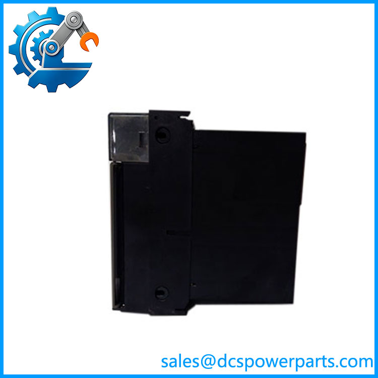
TK-PRR021
Frequently Asked Questions
What is Honeywell TK- used for?
The TK- is a redundancy module for Honeywell controller systems. It supports the redundant-controller architecture rather than executing the user’s DCS application itself. Published specifications identify it as a redundancy module and state that it uses two chassis slots.
Its role should therefore be understood as:
- Supporting the redundant controller arrangement
- Providing the required redundancy hardware interface
- Operating within the chassis architecture
- Supporting continued control availability when configured correctly
What is the part number for TK-?
The commonly documented complete identification is TK- / 51309288-275.
For procurement, I recommend recording the model and part number together. If the installed module has a revision suffix, capture that from the physical nameplate as well.
Does TK- support redundancy?
Yes. controller redundancy is the primary application of the module.
The important qualification is that the module alone does not create redundancy. The controllers, chassis, communication connections, firmware, configuration, and redundancy hardware must all be compatible.
What is the power requirement of TK-?
The published electrical data lists:
- 24 VDC: 90 mA
- 5 VDC: 1.0 A
- 3.3 VDC: 0.75 A
- 1.2 VDC: 0.007 A
It also occupies two chassis slots.
When calculating cabinet power requirements, do not use only the 24 VDC figure; the internal supply requirements are also relevant to the chassis power budget.
Can I hot-swap TK-?
Do not assume that it can be removed from an energized chassis.
A redundant controller architecture may allow maintenance without losing process control, but physical module removal is governed by the specific chassis, redundancy state, maintenance procedure, and system documentation. Before removal, confirm that the standby path is healthy and that the planned intervention cannot compromise the active controller.
Will replacing TK- erase my control logic?
The TK- is a redundancy module, not the primary storage location for the complete control application.
Before replacement, however, document:
- controller firmware.
- Active/standby status.
- Redundancy configuration.
- Chassis arrangement.
- Network configuration.
- Application backup.
- Diagnostic status.
A proper backup remains essential because the redundancy module and controller configuration are part of one operating architecture.
Does TK- require firmware matching?
The module itself should not be evaluated in isolation. Controller firmware, Experion PKS release, redundancy configuration, and the installed chassis architecture all need to be considered together.
For an existing plant, record the firmware and system release before ordering a replacement. If the replacement has a different hardware revision, validate it in a controlled test environment rather than assuming functional equivalence from the model number alone.
How should a New Surplus TK- be tested?
A useful acceptance test should verify redundancy functionality, not just power-up.
Recommended procedure:
- Confirm TK- / 51309288-275 identification.
- Record hardware revision.
- Inspect connectors and chassis interface.
- Verify the two-slot installation requirement.
- Install the module in a compatible test chassis.
- Confirm normal power and diagnostic indications.
- Install the appropriate redundant-controller configuration.
- Verify communication between the redundant controller paths.
- Confirm primary/standby status.
- Perform a controlled redundancy transfer.
- Check controller diagnostics after transfer.
- Restore the intended operating configuration.
- Record all test results.
Procurement note: the critical acceptance point is not simply whether the TK- powers up. The spare should demonstrate that it participates correctly in the redundancy architecture under a controlled test.