Description
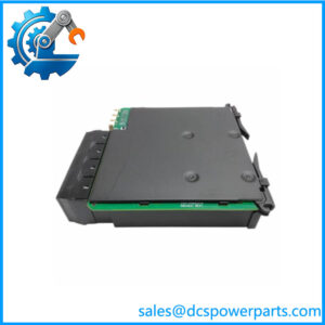
GE IS200EXHSG3REC | Exciter High-Speed Relay Driver Board | EX2100
Key Technical Specifications
| Parameter | Specification |
|---|---|
| Manufacturer | GE General Electric |
| Model | IS200EXHSG3REC |
| Functional Acronym | EXHS |
| Product Family | Excitation Control |
| Control Platform | Mark VI |
| Board Function | Exciter High-Speed Relay Driver |
| Board Group | G3 |
| PCB Revision | REC |
| Primary Role | High-speed relay/contactors control and status conditioning |
| Associated Controller Board | IS200EMIO |
| Backplane Interface | IS200EBKP Exciter Backplane |
| Application | Static excitation / generator excitation |
| PCB Coating | Normal coating |
| Installation | Mark VI exciter cabinet / associated exciter assembly |
GE documentation references and technical cross-references identify the IS200EXHSG3 family as an Exciter High-Speed Relay Driver Board used in systems. The board provides driver and feedback functions associated with DC contactors, field flashing, de-excitation, and crowbar-related status signals.
Important specification note: Public sources contain conflicting electrical ratings for the exact suffix. I would not publish generic 24 VDC input, 10 kHz sampling, ±10 V analog input, IEC 61850, or similar figures for this board. Those claims appear to result from incorrect product mapping. The exact system schematic and board documentation should be used for circuit-level ratings.
Product Introduction
The is an EXHS Exciter High-Speed Relay Driver Board developed for GE’s excitation-control architecture within the Mark VI turbine control family. Its job is fundamentally different from that of a conventional PLC I/O module: it provides the relay-driver and signal-conditioning functions required by the static excitation system, including control and monitoring associated with DC contactors and excitation protection circuits.
The belongs to the G3 variant of the EXHS board family. The EXHS architecture is designed for high-speed excitation applications and uses solid-state relay-driver circuitry rather than the conventional contactor arrangement associated with the EXTB family. The board connects into the exciter control architecture through the IS200EBKP backplane and communicates with the redundant or simplex IS200EMIO control interface depending on system configuration.
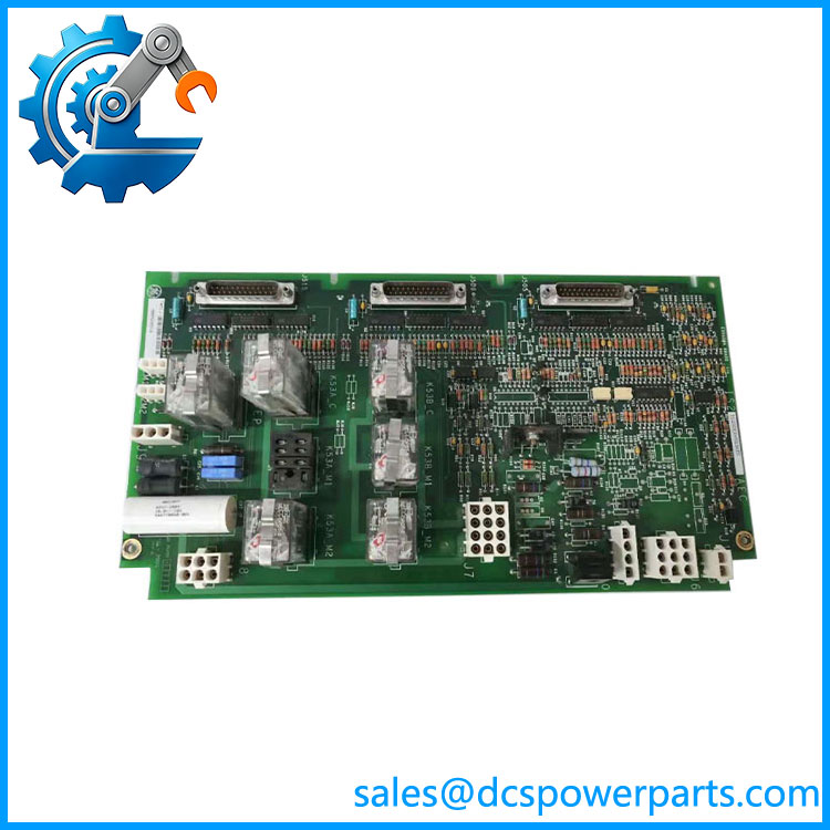
IS200EXHSG3REC
Application Scenarios & Field Pitfalls — The Engineer’s Perspective
Engineering Pain Point
A failed relay-driver board in an excitation system can create a much bigger problem than a normal discrete-I/O failure. The EXHS board sits directly in the control path for excitation-related switching and feedback, so a replacement must match the installed exciter architecture, board group, and revision. A board that physically fits the cabinet is not automatically a valid substitute.
Typical Applications
- Generator excitation systems — part of GE static excitation control installations.
- Steam turbine generators — supports excitation switching, field flashing, and de-excitation-related circuitry.
- Gas turbine generator packages — used within GE generator excitation control cabinets.
- Hydroelectric generator excitation — applicable to installations where high-speed excitation switching is required.
- Legacy Mark VI turbine-control maintenance — replacement of failed or degraded EXHS hardware during planned outages.
Technical Pitfalls to Avoid
- Do not confuse EXHS with a high-speed analog input board.
Some online listings describe the as a high-speed synchronized input module with ADC channels, PLL functions, IEC 61850, and PMU capabilities. Those specifications do not match the documented EXHSG3 function. The EXHSG3 family is a high-speed relay-driver board for the exciter. - Check the complete revision suffix.
The G3 designation identifies a specific EXHS board group. The final revision characters are also important when comparing replacement inventory. Do not approve an IS200EXHSG1, G4, or a different EXHS revision simply because the boards appear mechanically similar. - Understand the EXHS versus EXTB distinction.
The EXHS board is intended for high-speed excitation applications and uses solid-state relay-driver circuitry. GE technical references distinguish this architecture from the EXTB arrangement. Substituting an EXTB into a high-speed application can therefore change the switching architecture rather than simply replacing an equivalent board. - Inspect the associated EMIO and EBKP interfaces.
EXHSG3 does not operate as an independent PLC module. Its signals are integrated into the exciter architecture through the exciter backplane and EMIO control boards. A board-level fault diagnosis should therefore include connector condition, backplane connections, relay-driver circuitry, and associated field wiring. - Pay attention to relay and contactor feedback.
The EXHS architecture includes monitoring associated with the 41 contactor, field-flashing relays, and de-excitation/crowbar circuitry. Incorrect feedback can produce a control-system fault even when the driver board itself appears operational. - Handle the PCB as excitation-system hardware, not ordinary I/O.
Anti-static handling, correct isolation procedures, and adherence to the generator excitation system’s maintenance procedure are important. The board can be connected to circuits associated with high-energy excitation equipment.
Related Products
- GE IS200EXHSG3A / IS200EXHSG3AEC — same G3 EXHS board family; the AEC version is a documented G3 Exciter High-Speed Relay Driver variant. Verify revision and complete functional part number before interchange.
- GE IS200EXHSG1AEC — G1 EXHS High-Speed Static Exciter Board; similar family function but different group configuration.
- GE IS200EXHSG4AEC — G4 EXHS Exciter High-Speed Relay Driver Board; related family member with a different group designation.
- GE IS200EXHSG1AEB — earlier G1 EXHS revision; useful when tracing legacy board configurations.
- GE IS200EXTB — conventional exciter terminal-board family; functionally related but not automatically interchangeable with EXHS high-speed hardware.
- GE IS200EMIO — Exciter Main I/O board that receives and processes signals associated with the EXHS architecture.
- GE IS200EBKP — Exciter Backplane Board used to interconnect the EXHS and other exciter boards.
- GE IS200EDEXG1A — Exciter De-Excitation Board used for de-excitation functions; it works in conjunction with EXHS-related circuitry but is not a relay-driver replacement.
- GE Excitation Control — the system platform in which the EXHS family performs its excitation relay-driver function.
Procurement note: Specify the complete number when sourcing a replacement. For a shutdown-critical excitation application, also record the board’s functional revision, artwork revision, coating type, installed configuration, and the corresponding EMIO/EBKP hardware. This is much safer than matching only the “EXHS” family name.