Description
Product introduction
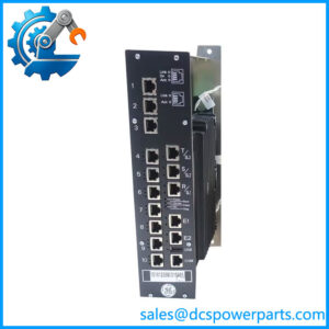
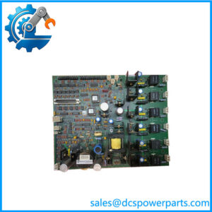
In an EX2100 excitation regulator, unstable internal supply rails can affect controller operation, feedback circuits, relay functions, and other excitation-system equipment. The GE IS200EPSMG2A addresses this requirement by converting the regulator DC-link input into the multiple power outputs needed by the regulator assembly. Its buck-regulator and push-pull inverter stages provide the conversion and transformer isolation used by the power-supply design.
The EPSMG2 is intended for regulator control, and its integrated EPSD daughterboard modifies the power-input path and adds input fuse protection. In simplex installations, one module is used in the regulator backplane; redundant configurations use modules in the main and redundant regulator backplanes. Before replacing the unit, verify the DC-link source, backplane location, output rails, and exact hardware revision against the installed system documentation.
Key technical specifications
| Parameter | Specification |
|---|---|
| Product model | IS200EPSMG2A |
| Manufacturer | General Electric |
| Product series | EX2100 excitation control |
| Functional acronym | EPSM |
| Product type | Exciter regulator power supply module |
| Input source | Regulator DC-link bus; confirm the actual input conditions in the system manual |
| Conversion topology | Buck regulator followed by push-pull inverter |
| Main output rails | +5 V DC, ±15 V DC, +24 V DC |
| Additional outputs | ±24 V DC, isolated +70 V DC, ±55 V DC, and 20 V AC at 25 kHz for specified circuits |
| Daughterboard | EPSD, integrated with the Group 2 assembly |
| Backplane installation | ERBP or ERRB, depending on simplex or redundant architecture |
| Protection | EPSD input fuse; individual output protection is provided on documented configurations |
| Communication protocol | Not a standalone network communication module |
| Operating temperature | A secondary listing states −30°C to +65°C; verify the applicable GE documentation for the installed revision |
| Protection rating | No verified IP rating for this board |
| Operating accuracy | Not applicable as a standalone signal-measurement specification |
The output list describes the documented EPSMG2 architecture. Exact output tolerances, current limits, fuse ratings, and input limits should be checked in the applicable GEI-100462 documentation before testing or installation.
Major features and advantages
- Multiple regulated supply rails: Provides the voltage groups needed by the EX2100 regulator backplane and connected excitation-system circuits.
- Input-path protection: The EPSD daughterboard includes a fuse in the DC-link input path, adding a defined protection point for the regulator supply circuit.
- Transformer isolation: The push-pull conversion stage uses a transformer to isolate the input from the generated outputs.
- Support for redundant configurations: The module can be installed in the main and redundant regulator backplanes in systems designed for redundant operation.
- Power distribution beyond the controller: Additional rails support specified loads such as fans, relays, contact-wetting circuits, dynamic-discharge equipment, and ground-detection circuits.
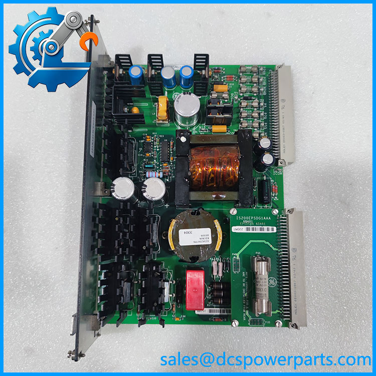
IS200EPSMG2A
IS200EPSMG2A
Application scenarios and common pain points
The IS200EPSMG2A is used in GE EX2100 regulator-control installations associated with generator excitation systems.
Common maintenance concerns include:
- Controller power faults: Measure the documented output rails at approved test points and compare them with the manual’s limits.
- Repeated fuse failures: Investigate input conditions, downstream short circuits, and connected loads before replacing a fuse.
- Redundant-system alarms: Check the relevant EPSM, backplane, input supply, and status indicators rather than assuming the module itself is faulty.
- Incorrect module substitution: EPSMG1 and EPSMG2 serve different system functions and should not be treated as interchangeable.
- Unverified replacement condition: Confirm the daughterboard is present and correctly seated, and request documented functional testing where available.
Related products
| Model | Function or relationship |
|---|---|
| IS200EPSMG1A | EPSM Group 1 power-supply module for a different EX2100 application |
| IS200EPSDG_A | EPSD regulator power-supply daughterboard family |
| IS200EPDMG1A | Exciter power distribution module family |
| IS200ERBPH_A | Exciter regulator backplane family |
| IS200ERRBH_A | Exciter regulator redundant backplane family |
| IS200EDCFG1A | DC feedback module family |
| IS200EDEXG1A | De-excitation module family |
| IS200EGDMG1A | Ground-detector module family |
These products are related to the broader EX2100 excitation architecture; they are not direct substitutes for the IS200EPSMG2A. Confirm the exact assembly code and revision before ordering.
Engineer’s guide before ordering
- Confirm the full part number. Check the IS200EPSMG2A label and any additional assembly or revision suffixes.
- Verify the electrical interface. Confirm the DC-link source, backplane position, output rails, and system configuration using the correct GE manual.
- Check the module and daughterboard. Inspect connectors, fuses, capacitors, and the EPSD assembly. Request functional-test records and the condition classification for used or refurbished units.
Safety warning: The module is part of a power-conversion system. Follow approved isolation and discharge procedures before handling it, and do not test the DC-link input without the required equipment and qualified personnel.
Frequently asked questions
What is the GE IS200EPSMG2A used for?
It converts the DC-link input into the supply rails required by the GE excitation regulator control system and associated circuits.
What is the difference between IS200EPSMG1A and ?
The Group 1 module serves a different excitation-control application, while the Group 2 module is designed for regulator control and includes the EPSD input daughterboard. They should not be substituted without explicit system-level approval.
What output voltages does the provide?
The documented architecture includes +5 V DC, ±15 V DC, +24 V DC, additional ±24 V DC rails, isolated +70 V DC, ±55 V DC, and a 20 V AC, 25 kHz output for specified applications. Check the manual for the applicable configuration and output limits.
What input voltage does this module require?
It receives DC-link power from the regulator power source. Do not assume a generic AC input or apply a voltage based on unrelated power-supply listings; verify the DC-link specification for the installed system.
Can it be used in a redundant excitation regulator?
Yes, the documented architecture uses EPSMG2 modules in the main and redundant regulator backplanes for redundant configurations. The actual arrangement depends on the system design.
What should be checked when buying a replacement?
Confirm the full model and suffix, daughterboard presence, connector condition, fuse condition, functional-test scope, warranty, and compatibility with the installed regulator backplane.
What information should be included in a quotation request?
Provide , quantity, required condition, delivery destination, and any testing or warranty requirements. Ask the supplier to confirm stock status and dispatch timing before coordinating a planned shutdown.