Description
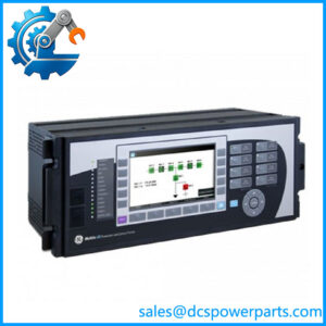
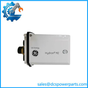
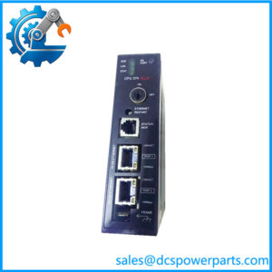
GE Multilin F650-B-F-J-F1-G1-HI-6H-E Feeder Protection Relay
Product Introduction
The GE Multilin F650-B-F-J-F1-G1-HI-6H-E is a digital feeder protection relay from GE Multilin’s F650 platform, designed for protection, control, monitoring and automation of electrical distribution feeders. It is an intelligent electronic device (IED), not a conventional PLC or DCS input/output module. The F650 platform combines protection algorithms, breaker control, measurement, event recording, programmable logic and communications within a dedicated feeder-protection architecture. Exact capabilities depend on the hardware and software configuration represented by the complete order code.
The GE F650-B-F-J-F1-G1-HI-6H-E is intended for applications where feeder protection and substation automation need to be handled in the same device. Typical F650 functions include phase and ground overcurrent protection, voltage and frequency protection, breaker failure functions, autoreclosing, programmable control logic, metering and disturbance/event recording. The relay can interface with CT and VT circuits and provide configurable binary inputs and outputs for breaker status, trips, alarms and interlocking. These capabilities make the F650 useful at the feeder level where protection decisions must remain local even when supervisory information is exchanged with a plant or substation automation system.
For engineers evaluating F650-B-F-J-F1-G1-HI-6H-E as a replacement, the complete ordering code should be treated as part of the electrical specification. F650 relays were offered with different communications, power-supply, I/O and protection configurations. Generic claims that every supports every listed protocol or protection option are not sufficient for a replacement decision. Before procurement, compare the nameplate, hardware revision, firmware, CT/VT input arrangement, binary I/O, communication ports, protection setting file and existing relay configuration. This is particularly important when the device is installed in an operating protection scheme where a superficially similar can still have materially different hardware.
Technical Specifications
| Specification | Details |
|---|---|
| Product Model | -B-F-J-F1-G1-HI-6H-E |
| Manufacturer | GE Multilin / General Electric |
| Product Family | Multilin |
| Product Type | Digital feeder protection relay / bay controller |
| Primary Application | Distribution feeder protection and control |
| System Role | Protection IED |
| Current Inputs | CT inputs; exact quantity/rating must be verified from the order-code documentation |
| Voltage Inputs | VT inputs; exact configuration must be verified |
| Digital Inputs | Configurable binary inputs; exact quantity depends on hardware configuration |
| Digital Outputs | Configurable relay outputs; exact quantity depends on hardware configuration |
| Protection | Overcurrent, ground fault and other feeder protection functions depending on configuration |
| Breaker Functions | Breaker control, breaker failure and related automation functions depending on configuration |
| Communications | platform supports serial/Ethernet communication options; exact interfaces must be verified for this suffix |
| Protection Setting Software | GE Multilin engineering/configuration environment |
| Display | Front-panel LCD/HMI with programmable indicators |
| Mounting | Panel / relay case installation |
| Operating Temperature | documentation/configuration should be checked for the exact hardware revision before specifying a project limit |
| Protection Rating | Depends on the complete relay/case configuration; do not infer an enclosure IP rating from the family name |
Specification note: Current web listings commonly publish a 24–250 VDC / 48–240 VAC supply range and −40 to +70 °C operating range for this part number, but these figures are not sufficiently well supported by an original GE configuration document for me to treat them as exact suffix-specific specifications. For procurement, verify the relay nameplate and GE order-code documentation rather than copying generic -family values.
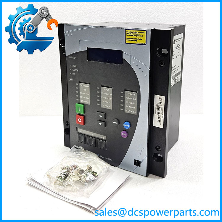
F650-B-F-J-F1-G1-HI-6H-E
Main Features and Engineering Considerations
Feeder Protection IED
The is designed around electrical protection rather than general automation. Its processing continuously evaluates measured current and voltage quantities and applies configured protection elements. This makes it appropriate for feeder protection schemes where local relay operation must remain available even if supervisory communications are unavailable.
Protection and Control in One Device
Depending on the installed configuration, the can combine protection elements with breaker control, interlocking, autoreclosing and programmable logic. This reduces the amount of separate control hardware required at the feeder level, but it also means that replacement work has to consider both the protection scheme and the control scheme.
Measurement and Disturbance Analysis
-family devices support electrical metering and event/disturbance recording functions. These records can be valuable when investigating feeder trips because engineers can compare relay operation against the measured electrical quantities and sequence of events rather than relying only on breaker status indications.
Communications
The platform supports substation communication through serial and Ethernet interfaces, with protocol options including Modbus, DNP3 and IEC 61850 in applicable configurations. Do not assume that all three are physically present on F650-B-F-J-F1-G1-HI-6H-E without verifying the original configuration.
Configuration Is Part of the Equipment
A protection relay should not be evaluated only as a hardware replacement. CT ratios, VT ratios, phase sequence, pickup values, time curves, directional settings, breaker logic, autoreclose sequences, binary input assignments and communication mappings all affect system behavior.
A replacement relay with the same family name but different hardware or firmware can require engineering changes even when it fits mechanically.
Application Scenarios
- Medium-voltage distribution feeders
- Industrial electrical distribution systems
- Utility feeder protection
- Substation feeder protection and automation
- Transformer secondary feeder protection
- Motor or process-plant distribution feeders
- Breaker control and interlocking applications
- Substation monitoring and event recording
- Retrofit projects involving legacy GE Multilin installations
Engineer’s Guide: Field Pitfalls
1. Do not treat the as a PLC.
Its primary role is electrical protection. PLC-style logic is available for automation, but the protection elements and trip logic have different engineering requirements.
2. Verify the complete order code.
The difference between suffixes can represent hardware, communication, power or I/O configuration changes. The complete designation should appear on the procurement specification.
3. Check CT and VT circuits before replacement.
CT ratio, nominal current, grounding arrangement, phase sequence and VT configuration must match the protection study and existing wiring. Never assume that physically compatible terminals mean electrically compatible CT/VT inputs.
4. Preserve the existing protection settings.
Download and archive the relay settings, logic, oscillography/event configuration and communication parameters before removing the existing device.
5. Check firmware compatibility.
A settings file created for one firmware revision may not behave identically after migration to another revision. Validate the configuration in the intended engineering software before energizing the replacement.
6. Verify breaker logic separately.
Trip outputs, close outputs, breaker auxiliary contacts, lockout relay interfaces and interlocking logic should be tested independently. A protection relay can pass a communications test while still having incorrect breaker control wiring.
7. Do not assume every has IEC 61850.
The family offered multiple communication configurations. Confirm the actual rear-panel ports and order-code options before specifying IEC 61850, DNP3 or Modbus integration.
8. Test the protection scheme, not just the relay.
Secondary injection should cover the actual protection elements used by the feeder study. Binary I/O, trip circuits, breaker feedback, interlocks and communication alarms should also be tested before returning the feeder to service.
Frequently Asked Questions
What is the GE ?
It is a GE Multilin digital feeder protection relay / bay controller used for electrical feeder protection, control, measurement and automation.
Is the a PLC?
No. It is an electrical protection IED. Although it provides programmable logic and automation functions, its primary engineering purpose is feeder protection and breaker control.
What protection functions are available?
The platform supports functions such as phase and ground overcurrent, voltage and frequency protection, breaker failure, autoreclosing and other feeder protection functions. The exact enabled elements depend on the particular hardware, firmware and configuration.
Does this support IEC 61850?
The family was offered with IEC 61850 communication capability, but the exact communication hardware installed in should be confirmed before specifying IEC 61850 for a project. Do not infer the communication option from the family name alone.
Can it control a circuit breaker?
Yes. Breaker control, interlocking and related automation are part of the platform’s capabilities, subject to the particular configuration and application logic.
What should be checked before replacing an existing ?
At minimum, verify the complete order code, hardware revision, firmware, CT/VT arrangement, binary I/O, communications hardware, protection settings, programmable logic, breaker control wiring and communication mapping.
Is suitable for a DCS application?
It can interface with a plant DCS or substation automation system, but it should remain the dedicated protection IED. The DCS should not be treated as a substitute for the relay’s local protection functions.
Procurement Note
For , the safest procurement approach is to match the complete nameplate order code and existing configuration, not simply purchase another relay.
For an installed feeder, request or preserve the original relay settings file, firmware revision, protection study, CT/VT ratios, binary I/O assignment, breaker logic and communication configuration. If the replacement is supplied with a different hardware or firmware revision, perform a configuration comparison before field installation.
The most important acceptance test is not simply that the relay powers up and communicates. The replacement should be proven against the actual protection scheme through appropriate secondary injection, binary I/O testing, trip-circuit verification, breaker feedback testing and communications validation.